MAN truck FFR On-board computer Fault codes list
See also:
- MAN Truck Fault codes engine control unit (EDC)
- MAN – Engine control unit fault codes (EDC7 Common-rail)
MAN FFR
| Code (SPN) | Description | The reason, check and reaction of the system. |
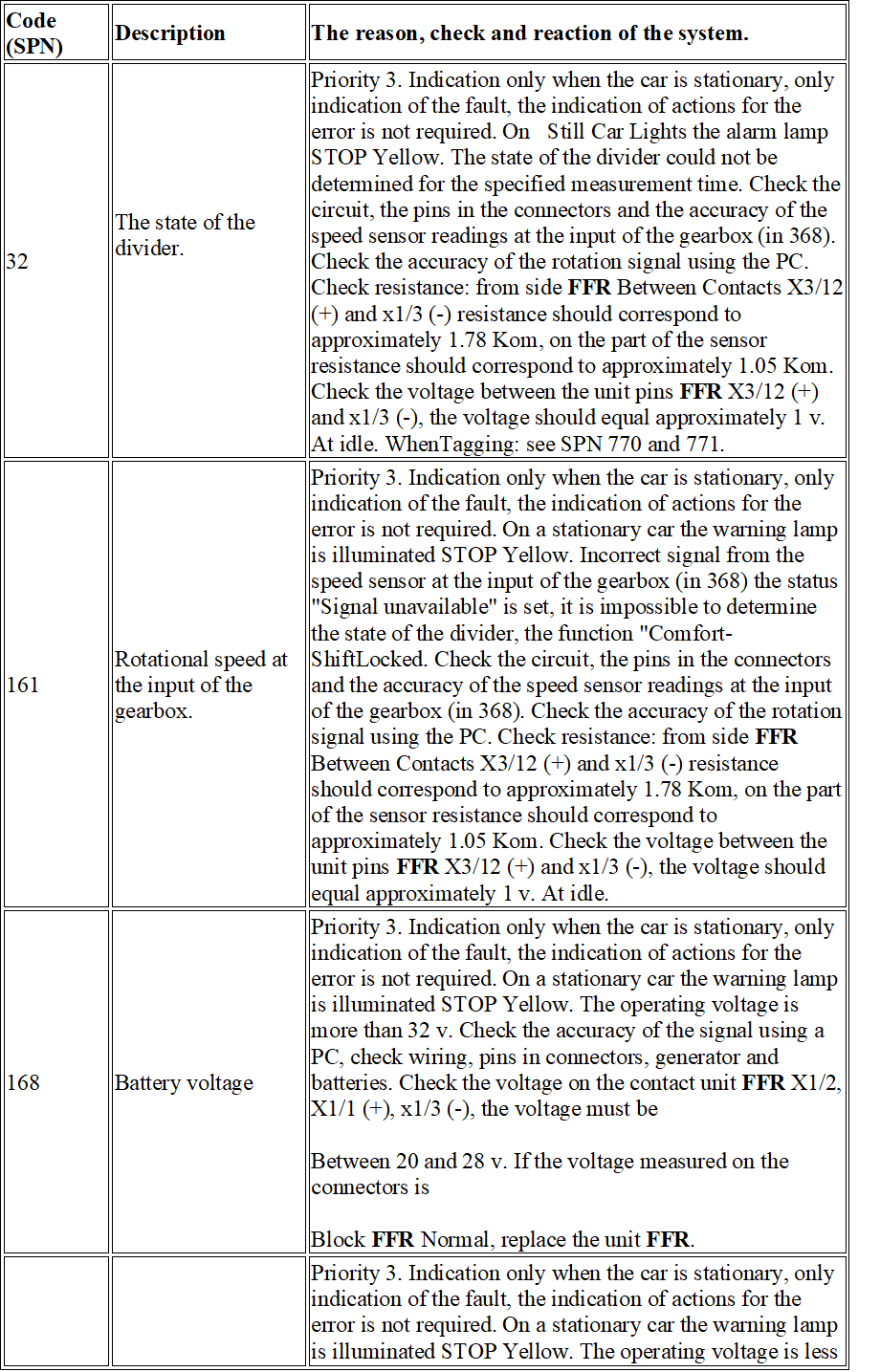
| 32 | The state of the divider.
|
Priority 3. Indication only when the car is stationary, only indication of the fault, the indication of actions for the error is not required. On Still Car Lights the alarm lamp STOP Yellow. The state of the divider could not be determined for the specified measurement time. Check the circuit, the pins in the connectors and the accuracy of the speed sensor readings at the input of the gearbox (in 368). Check the accuracy of the rotation signal using the PC. Check resistance: from side FFR Between Contacts Х3/12 (+) and х1/3 (-) resistance should correspond to approximately 1.78 Kom, on the part of the sensor resistance should correspond to approximately 1.05 Kom. Check the voltage between the unit pins FFR Х3/12 (+) and х1/3 (-), the voltage should equal approximately 1 v. At idle. WhenTagging: see SPN 770 and 771. |
| 161 | Rotational speed at the input of the gearbox. | Priority 3. Indication only when the car is stationary, only indication of the fault, the indication of actions for the error is not required. On a stationary car the warning lamp is illuminated STOP Yellow. Incorrect signal from the speed sensor at the input of the gearbox (in 368) the status “Signal unavailable” is set, it is impossible to determine the state of the divider, the function “Comfort-ShiftLocked. Check the circuit, the pins in the connectors and the accuracy of the speed sensor readings at the input of the gearbox (in 368). Check the accuracy of the rotation signal using the PC. Check resistance: from side FFR Between Contacts Х3/12 (+) and х1/3 (-) resistance should correspond to approximately 1.78 Kom, on the part of the sensor resistance should correspond to approximately 1.05 Kom. Check the voltage between the unit pins FFR Х3/12 (+) and х1/3 (-), the voltage should equal approximately 1 v. At idle. |
| 168 | Battery voltage | Priority 3. Indication only when the car is stationary, only indication of the fault, the indication of actions for the error is not required. On a stationary car the warning lamp is illuminated STOP Yellow. The operating voltage is more than 32 v. Check the accuracy of the signal using a PC, check wiring, pins in connectors, generator and batteries. Check the voltage on the contact unit FFR Х1/2, X1/1 (+), х1/3 (-), the voltage must be
Between 20 and 28 v. If the voltage measured on the connectors is Block FFR Normal, replace the unit FFR. |
|
168 |
battery power supply voltage. |
Priority 3. Indication only when the car is stationary, only indication of the fault, the indication of actions for the error is not required. On a stationary car the warning lamp is illuminated STOP Yellow. The operating voltage is less than 16 v. Check the accuracy of the signal using a PC, check wiring, pins in connectors, generator and batteries. Check the voltage on the contact unit FFR Х1/2, Х1/1 (+), х1/3 (-), the voltage should be within the limits between 20 and 28 v. If the voltage measured on the connectors of the Unit FFR Normal, replace the unit FFR. |
|
572 |
Auxiliary device for the activation of the retarder brake. |
Priority 5: Indication during stop and during vehicle movement. Signal Lamp STOP is lit in yellow and during movement and during stop or parking. The wiring of the data line from the touch control switch to the retarderer is faulty. The switch stops functioning. The included brake retardeactivates by pressing the accelerator pedal. Check the accuracy of the signal using the PC, check the wiring, pins in the connectors, touch the brake-retarderer. Check the resistance of the data transmission line from the touch switch, between the unit pins FFR Х2/10 (+) and х1/3 (-) on the side of the block FFR Approx. 1.5 PTO, on the car side approximately 1.6 pto. Check the wire resistance of the touch switch of the retarder, between the pins of the unit FFR X2/6 (+) and x 1/3 (-) on the side of the block FFR Approximately 1.7 IOM, on the side of the car approximately 1.2 IOM. Check the voltage of the data transmission line from the touch switch, between the unit pins FFR X2/10 (+) and х1/3 (-), jumper (test block) Closed: approx. 14.2 v., jumper (test block) Open: On the side of the unit FFR Approx. 23.5 in, on the side of the car approx. 14 v. Check the voltage of the timing wire of the retarder touch switch, between the unit pins FFR Х2/6 (+) and x 1/3 (-) jumper (test block) Closed: approx. 12.3 v., jumper (test block) Open: On the side of the unit FFR Approximately 13.5 v., on the side of the car approximately 22.5 v. |
|
697 |
Accelerator pedal, Signal PWM1 (signal pulse modulation). |
Priority 2: A malfunction that requires removal from the service center. Signal Lamp STOP Lights up permanently in red. Missing or incorrect signal PWM1 Accelerator pedal (a 410). To identify the position of the accelerator pedal, a signal is PWM2. Engine speed and torque are limited (1800 RPM and 80% limit). Check the accuracy of the signal PWM1 with PC, check wiring, pins in connectors. Perform measurement using a portable oscilloscope Fluke ScopeMeter 123 or similar device (frequency 200 Hz). Check the voltage on the unit FFR Between pins х2/11 (+) and х1/3 (-): The jumper (Test block) is closed, the signal Low: (The accelerator pedal is fully pressed) approx. 8 v., the Signal HIGH: approx. 20 v.; Jumper (test block) Open: On the side of the unit FFR Approx. 25.4 v., on the side of the car approx. 0.5 v. If the problem is not found, try recalibrating the accelerator pedal.
If the voltage drop when the ignition is on, the PWM1 (а410/pin5) and power supply on PWM2 (а410/pin6) is more than 100 MS, the fault code is registered. |
|
698 |
Accelerator pedal, Signal PWM2 (signal pulse modulation). |
Priority 2: A malfunction that requires removal from the service center. Signal Lamp STOP Lights up permanently in red. Missing or incorrect signal PWM2 Accelerator pedals (a 410). To identify the position of the accelerator pedal, a signal is PWM1. Engine speed and torque are limited (1800 RPM and 80% limit). Check the accuracy of the signal PWM2 using PC, check wiring, pins in connectors. Perform measurement using a portable oscilloscope Fluke ScopeMeter 123 or similar device (frequency 200 Hz). Check the voltage on the unit FFR Between pins х2/18 (+) and х1/3 (-): The jumper (Test block) is closed, the signal Low: approx. 8 v., Signal HIGH (Accelerator pedal is fully pressed): approx. 20 v.; Jumper (test block) Open: On the side of the unit FFR Approx. 25.5 v., from the car side approx. 0 v. If the problem is not found, try recalibrating the accelerator pedal.
If the voltage drop when the ignition is on, the PWM1 (а410/pin5) and power supply on PWM2 (а410/pin6) is more than 100 MS, the fault code is registered. |
|
770 |
Раздельный H. |
Priority 5: Indication during stop and during vehicle movement. Signal Lamp STOP is lit in yellow and during movement and during stop or parking. Malfunction in electromagnetic valve wiring detected SPLIT-HIGH (Y307). The malfunction is recorded in the fault recorder in case the malfunction is recorded during three cycles of measurement (500 ms). The divider valve stops being controlled.
Using a PC, you can test the elements “SPLIT-HIGHandSPLIT- LOW”. Check resistance between pins х3/13 (+) and х4/6 (-): On the side of the block FFR Approximately 6 Kom, on the car side approximately 83.3 ohm. Check resistance between pins х3/13 (+) and х1/3 (-): On the side of the block FFR approx. 4.3 com, on the side of the car —. Check the voltage between the unit pins FFR {3/13 (+) and х4/6 (-): At an activated electromagnetic valve approximately 27.6 v. At the deactivated valve approximately 0 v. |
| 771 | Раздельный. | Priority 5: Indication during stop and during vehicle movement. Signal Lamp STOP is lit in yellow and during movement and during stop or parking. Malfunction in electromagnetic valve wiring detected SPLIT-LOW (Y307). The malfunction is recorded in |
| Fault recorder in case the fault is registered during three cycles of measurement (500 ms). The divider valve stops being controlled. Using a PC, you can test the elements “SPLIT-HIGHandSPLIT- LOW”. Check resistance between pins х4/7 (+) and х4/6 (-): On the side of the block FFR Approximately 6 Kom, on the car side approximately 84.6 ohm. Check resistance between pins х4/7 (+) and х1/3 (-): On the side of the block FFR approx. 4.3 com, on the side of the car–
-. Check the voltage between the unit pins FFR {4/7 (+) and х4/6 (-): At an activated electromagnetic valve approximately 27.6 v. At the deactivated valve approximately 0 v. |
||
|
898 |
Group of resistors limit maximum speed. |
Priority 5: Indication during stop and during vehicle movement. Signal Lamp STOP is lit in yellow and during movement and during stop or parking. Incorrect signal from the group of resistors (R134). Stage HGB (maximum speed limit) remains activated. After the next turn, select the RGB0 (Maximum speed limit 1 is activated). With the help of PC check signal accuracy, check wiring, pins in connectors, check the body interface х1996, check the group of resistors (R134). Check the resistance between pins х2/6 (+) and х1/3 (-) on the side of the unit FFR Approximately 6.5 Kom, on the side of the car approximately 0.511 Kom. Check resistance of the group of resistors (R134): Between contacts 5 and 7/6 approximately 3.09 Kom, between contacts 5 and 3/4 approximately 1.37 Kom, between contacts 5 and 2/8 approximately 0.51 Kom, between contacts 5 and 1/9 approximately 8.2 kom.
Check the voltage between the unit pins FFR: х2/6 (+) and х1/3 (-) approximately 460 mv. |
|
1045 |
The final stage of the transmission lock. |
Priority 5: Indication during stop and during vehicle movement. Signal Lamp STOP is lit in yellow and during movement and during stop or parking. Closure of the lock on the output of the transmission (end stage) of the electromagnetic valve block (Y307). The transmission lock is no longer controlled. Check with PC the actuators (lock on transmission), wiring, pins in connectors. On gearboxes type ZF16S151/ZF16S181 Check the block of electromagnetic valves (Y307). Check the resistance between the pins x 4/13 (+) and х3/5 (-): On the side of the unit FFR Approximately 8.9 ohm, on the side of the car approximately 135 ohms. Check resistance between pins х4/13 (+) and x 1/3 (-): On the side of the block FFR Approx. 8.3 Kom, on the side of the car—. Check the voltage between pins х4/13 (+) and х3/5 (-): When an electromagnetic valve is activated approximately 27.5 v., when The solenoid valve is deactivated by approx. 0 v. |
|
3010 |
Limit the speed and torque. |
Priority 5: Indication during stop and during vehicle movement. Signal Lamp STOP is lit in yellow and during movement and during stop or parking. Incorrect signal from the group of resistors (R134). The limit level for the speed range remains activated. At the first turn, step 0 is activated for the engine speed range. With the help of PC check signal accuracy, check wiring, pins in connectors, check the body interface х1996, check the group of resistors (R134). Check the resistance between pins х2/1 (+) and х1/3 (-): On the side of the block FFR Approximately 6.5 ohm, on the side of the car approximately 0.511 ohms. Check resistance of the group of resistors (R134): Between contacts 5 and 7/6 approximately 3.09 Kom, between contacts 5 and 3/4 approximately 1.37 Kom, between contacts 5 and 2/8 approximately 0.51 Kom, between contacts 5 and 1/9 approximately 8.2 kom. Check the voltage between the unit pins FFR: х2/1 (+) and х1/3 (-) approximately 460 mv. |
|
3020 |
Calibration value, accelerator pedal, PWM1. |
Priority 3. Indication only when the car is stationary, only indication of the fault, the indication of actions for the error is not required. On a stationary car the warning lamp is illuminated STOP Yellow. Signal PWM1 Accelerator pedal (a 410) is not set or configured. A malfunction occurs when the idle value is greater than 10% or less than 30%, and the full load point value is greater than 90% or less than 40%. The engine speed limit and torque limit are activated. The accelerator pedal value is calculated by the signal PWM2. Check the accuracy of the signal (pedal module PWM1) using the PC, calibrate the accelerator pedal. The pedal is calibrated using a PC. To calibrate, press the accelerator pedal to the end (the “boil down” mode must be activated), hold the pedal in the pressed position for about 3 seconds, then the pedal should be released, repeat these steps 2-3 times. When installing a new accelerator pedal, calibration is always required. |
|
3021 |
Calibration value, accelerator pedal, PWM2. |
Priority 3. Indication only when the car is stationary, only indication of the fault, the indication of actions for the error is not required. On a stationary car the warning lamp is illuminated STOP Yellow. Signal PWM2 Accelerator pedals (a 410) are not set or configured. A malfunction occurs when the idle value is less than 10% or greater than 30%, and the full load point value is greater than 90% or less than 40%. This activates the engine speed limit and torque limit. The accelerator pedal value is calculated by the signal PWM1. Check the accuracy of the signal (pedal module PWM2) using the PC, calibrate the accelerator pedal. The pedal is calibrated using a PC. To calibrate, press the accelerator pedal to the end (the “boil down” mode must be activated), hold the pedal in the pressed position for about 3 seconds, then the pedal should be released, repeat these steps 2-3 times. When installing a new accelerator pedal, calibration is always required. |
| 3197 | Data bus CAN: Message AS-Tronic ETC1, byte 1. | Priority 3. Indication only when the car is stationary, only indication of the fault, the indication of actions for the error is not required. On a stationary car the warning lamp is illuminated STOP Yellow.
Incorrect signal values “shift process”or signal”driveline engaged”Control unit AS-Tronic (and 330). The incoming signal is identified as invalid. Check the fault recorder of the gearbox control unit AS-Tronic (a 330) and eliminate the causes of malfunctions, check wiring, pins in connectors. Check Data channel resistance CAN TransmissionT-CAN): On the contacts of the control unit AS-Tronic А12 (-) and а8 (+) approx. 60 ohm. Check Data channel resistance CAN TransmissionT-CAN) on the contacts of the Unit FFR Х1/15 (-) IH1/14 (+) approx. 120 ohm. At the resistance 0 Ohm can-High closure on Can-Low. |
|
3250 |
Comfort Shift Inputs (CS1 and CS2). |
Priority 5: Indication during stop and during vehicle movement. Signal Lamp STOP is lit in yellow and during movement and during stop or parking. The input value is not accurate when both input signals are Comfort Shift Gearbox Control switch (S477) have the same level longer than 100 Ms. or after enabling the request remains unfulfilled for longer than 2 S. function Comfort Shift Blocked. Using the PC, check the accuracy of the signal “switch Comfort Shift”and” switch Comfort Shift In the opposite position. ” Check Resistance: request Comfort Shift 1, Block FFR Between pins х2/12 (+) and х1/3 (-) on the side of the block FFR Approximately 4.6 com. Check Resistance: request Comfort Shift 2, Block FFR Between pins х2/3 (+) and х1/3 (-) on the side of the block FFR Approximately 4.6 com. Check Voltage: Request Comfort Shift 1, Block FFR Between pins х2/12 (+) and х1/3 (-): The switch is open 0 V, the switch is closed UCL. 15 (equal to the voltage on the terminal 15 of the ignition lock when ignition is on). Check Voltage: Request Comfort Shift 2, Block FFR Between pins х2/3 (+) and х1/3 (-): The switch is open 0 V, the switch is closed UCL. 15 (equal to the voltage on the terminal 15 of the ignition lock when ignition is on). |
|
3251 |
Switch FGR(Speed control System)/FGB(Speed limit). |
Priority 5: Indication during stop and during vehicle movement. Signal Lamp STOP is lit in yellow and during movement and during stop or parking. Switch malfunction FGR/FGB. System FGR Deactivated. Check with the PC the accuracy of the signal “switch FGR PpcTempomat) “, check the wiring and pins in the connectors, check the switch FGR/FGB (S284). Check Resistance: The switch is open, between the unit pins FFR Х2/16 (+) and х1/3 (-), block FFR Disconnected, approximately 4.6 com. Check voltage: The switch is open, between the unit pins FFR Х2/16 (+) and х1/3 (-), block FFR Disconnected 0 v. |
|
3269 |
Signal accuracy from the terminal 50 ignition lock (engine start). |
Priority 3. Indication only when the car is stationary, only indication of the fault, the indication of actions for the error is not required. On a stationary car the warning lamp is illuminated STOP Yellow. Signal about starting the engine from the ignition lock (Q101) is considered incorrect when the ignition is triggered, the engine start signal is fed. After the next procedure, the start is possible if a positive signal is detected during the engine start-up process. Using the PC, check the accuracy of the signal “terminal 50”, “External engine stop Request”, “External engine start request”, check wiring, pins in connectors, ignition lock (Q101), an external device for starting and stopping the engine.
Check the resistance between the pins of the Unit connector FFR Х3/7 (+) and х1/3 (-) on the side FFR Approximately 4.6 com. Check the voltage between Contacts Х3/7 (+) and х1/3 (-): The switch is open 0 v., the switch is closed from 16 to 32 V (UBattery voltage). |
|
3311 |
Control Unit (calibration amount EEPROM). |
Priority 1: Engine shutdown is required. Signal Lamp STOP Flashing red along with the symbol STOP. If the driver detects a malfunction, the unit FFR (a 403) must be replaced. If the malfunction appears after the programming process (e.g. key, clutch or accelerator pedal) or after replacing the unit FFR, you must change the settings again. If the unit FFR is replaced due to this malfunction, you need to do the following: Before connecting the PC, remove the faulty unit FFR, after connecting the PC using the menu item “from the service computer through the network connection in the enterprise” prepare the data required to replace the unit FFR, do not under any circumstances read data from a faulty unit FFR, it is possible to transfer the fault code 3311 to a new unit. |
| 3449 | Back pressure exhaust gas. | Priority 2: A malfunction that requires removal from the service center. Signal Lamp STOP Lights up permanently in red. The malfunction is recorded if the exhaust gas back pressure exceeds the threshold value during the specified time and the motor brake is not active. Module Evb (Engine brake Valve Y355) is deactivated. With the help of the PC check the accuracy of the signal “back pressure exhaust gas”, check the wiring, pins in connectors, module Evb. Check Resistance: Power 5 v., block FFR Between pins х2/5 (+) and х1/3 (-) on the side of the block FFR Approximately 100 Kom, on the side of the car approximately 3.7 kom. Check resistance: signal back pressure exhaust gas, block FFR Between pins Х3/4 (+) and х1/3 (-) on the side of the block FFR Approximately 100 Kom, on the side of the car approximately 12.2 kom. Check resistance: Mass, block FFR Between pins Х3/5 (+) and х1/3 (-) on the side of the block FFR Approximately 1.9 kom, on the side of the car approximately 54 Kom.
Check Resistance: Motor Brake, block FFR Between pins Х4/14 (+) and х1/3 (-) on the side of the block FFR Approx. 8.82 ohm, on the car side approximately 22 ohms. Check Voltage: Power supply 5 v., Unit FFR Between pins х2/5 (+) and x 1/3 (-) approx. 5 v. Check the voltage: signal back pressure exhaust gas, block FFR Between pins Х3/4 (+) and х1/3 (-) approximately 560 mv. Check voltage: Mass, block FFR Between pins Х3/5 (+) and х1/3 (-) 0v. Check voltage: Motor Brake, block FRR Between pins Х4/14 (+) and х1/3 (-) module Evb Activated—, module Evb Not activated 0 v. Check Voltage: Unit FFR Between pins х4/1 (+) and х3/5 (-) The electromagnetic valve is activated approximately 27.6 in, at simple signal HIGH Every 6 seconds, the solenoid valve is deactivated by 0 v. |
|
3450 |
Back pressure exhaust gas. |
Priority 2: A malfunction that requires removal from the service center. Signal Lamp STOP Lights up permanently in red. The malfunction is recorded if the exhaust gas back pressure exceeds the threshold value during the specified time and the motor brake is not active. Module Evb (Engine brake Valve Y355) is deactivated. With the help of the PC check the accuracy of the signal “back pressure exhaust gas”, check the wiring, pins in connectors, module Evb. Check Resistance: Power 5 v., block FFR Between pins х2/5 (+) and х1/3 (-) on the side of the block FFR Approximately 100 Kom, on the side of the car approximately 3.7 kom. Check resistance: signal back pressure exhaust gas, block FFR Between pins Х3/4 (+) and х1/3 (-) on the side of the block FFR Approximately 100 Kom, on the side of the car approximately 12.2 kom. Check resistance: Mass, block FFR Between pins Х3/5 (+) and х1/3 (-) on the side of the block FFR Approximately 1.9 kom, on the side of the car approximately 54 Kom.
Check Resistance: Motor Brake, block FFR Between pins Х4/14 (+) and х1/3 (-) on the side of the block FFR Approx. 8.82 ohm, on the car side approximately 22 ohms. Check Voltage: Power supply 5 v., Unit FFR Between pins х2/5 (+) and x 1/3 (-) approx. 5 v. Check the voltage: signal back pressure exhaust gas, block FFR Between pins Х3/4 (+) and х1/3 (-) approximately 560 mv. Check voltage: Mass, block FFR Between pins Х3/5 (+) and х1/3 (-) 0v. Check voltage: Motor Brake, block FRR Between pins Х4/14 (+) and х1/3 (-) module Evb Activated—, module Evb Not activated 0 v. Check Voltage: Unit FFR Between pins х4/1 (+) and х3/5 (-) The electromagnetic valve is activated approximately 27.6 in, at simple signal HIGH Every 6 seconds, the solenoid valve is deactivated 0 v. |
|
3451 |
“Comfort-Shift” is not functioning. |
Priority 5: Indication during stop and during vehicle movement. Signal Lamp STOP is lit in yellow and during movement and during stop or parking. functionComfort-ShiftLocked. Using the PC, check the accuracy of the signal “switch Comfort-Shift”and” switch Comfort-Shift In reverse position “, check wiring, pins in connectors, check switch control lever gearbox (S477). Check Resistance: request Comfort-Shift 1, Block FFR-Between pins х2/12 (+) and х1/3 (-) on the side of the block FFR Approximately 4.6 com. Check Resistance: request Comfort-Shift 2, Block FFR-Between Pins х2/3 (+) and х1/3 (-) on the side of the block FFR Approximately 4.6 com. Check Voltage: Request Comfort-Shift 1, Block FFR-Between pins х2/12 (+) and х1/3 (-) The switch is opened 0v., the switch is closed UCl15 (voltage from the ignition lock). Check Voltage: Request Comfort-Shift 2, Block FFR-Between Pins х2/3 (+) and х1/3 (-) The switch is opened 0v., the switch is closed UCl15 (voltage from the ignition lock). |
|
3452 |
Squeeze the clutch. |
Priority 5: Indication during stop and during vehicle movement. Signal Lamp STOP is lit in yellow and during movement and during stop or parking. The clutch is not pressed properly or the switch “Comfort-Shift”. It is necessary to keep the clutch pressed until the switching procedure is over. |
|
3510 |
Clutch overload. |
Priority 5: Indication during stop and during vehicle movement. Signal Lamp STOP is lit in yellow and during movement and during stop or parking. Block FFR Registered the clutch slip.
The torque decreases by 80%. After the specified time required to cool the clutch, the maximum torque is deblocked. |
|
3520 |
Timeout Lss1. |
Priority 5: Indication during stop and during vehicle movement. Signal Lamp STOP is lit in yellow and during movement and during stop or parking. The switch of the retarder/gearbox (a 942) does not answer the steering column. Using the PC, check the signal accuracy from the switch (A942), check wiring, pins in connectors, check the switch (a 942), check the fuse F583. Check the resistance of the signal wire between the unit contact FFR X2/8 and Contact 2 of the switch on the steering column: approx. 0.2 ohm. Check the voltage on the switch, the power supply of the tyre LIN Between pins 3 (+) and 1 (-) UBaht. (Battery voltage). |
|
3521 |
Timeout mfl1. |
Priority 5: Indication during stop and during vehicle movement. Signal Lamp STOP is lit in yellow and during movement and during stop or parking. No response from multifunction steering wheel MFL (a943). Using the PC to check the accuracy of signals from the multifunctional steering wheel MFL (a 943) (Set-, Set+, Off, Memo, FGR/FGB), check wiring, pins in connectors, check the steering wheel, check the fuse F583. Check the resistance of the bus signal wire LIN Between contact Х2/8 of the Unit FFR and 3 Steering wheel contact: approx. 0.2 ohm. Check bus power supply voltage LIN On Contacts 1 (+) and 2 (-): UBaht. (Battery voltage). Only the right side of the steering wheel can be checked using the PC. |
|
3522 |
Timeout inst1. |
Priority 5: Indication during stop and during vehicle movement. Signal Lamp STOP is lit in yellow and during movement and during stop or parking. No response from the dashboard (a 407). Check wiring, pins in connectors, check the dashboard (a 407). Check the resistance of the bus signal wire LIN Between contact Х2/8 of the Unit FFR and contact Х1/15 of the instrument panel: approx. 0.2 ohm. |
| 3524 | The right side of the MFL is faulty. | Priority 5: Indication during stop and during vehicle movement. Signal Lamp STOP is lit in yellow and during movement and during stop or parking. Right side of steering wheel MFL Defective. This problem is detected MFL And on THE Block FFR Message is transmitted MFL1.
With PC check the accuracy of signals from the multifunctional steering wheel MFL (a 943) (Set-, Set+, Off, Memo, FGR/FGB), check wiring, pins in connectors, check the steering wheel, check the fuse F583. Check the resistance of the bus signal wire LIN Between contact Х2/8 of the Unit FFR and 3 Steering wheel contact: approx. 0.2 ohm. Check bus power supply voltage LIN On Contacts 1 (+) and 2 (-): UBaht. (Battery voltage). Only the right side of the steering wheel can be checked using the PC. |
|
3525 |
Left/Right side MFL Not correct. |
Priority 5: Indication during stop and during vehicle movement. Signal Lamp STOP is lit in yellow and during movement and during stop or parking. Left/right side of steering wheel MFL Defective. This problem is detected MFL And on THE Block FFR Message is transmitted MFL1. With the help of PC check the accuracy of signals from the multifunctional steering wheel MFL (a 943) (Set-, Set+, Off, Memo, FGR/FGB), check wiring, pins in connectors, check the steering wheel, check the fuse F583. Check the resistance of the bus signal wire LIN Between contact Х2/8 of the Unit FFR and 3 Steering wheel contact: approx. 0.2 ohm. Check bus power supply voltage LIN On Contacts 1 (+) and 2 (-): UBaht. (Battery voltage). Only the right side of the steering wheel can be checked using the PC. |
|
3526 |
LSS malfunction. |
Priority 5: Indication during stop and during vehicle movement. Signal Lamp STOP is lit in yellow and during movement and during stop or parking. The switch of the retarder/gearbox (a 942) is not faulty steering column. Using the PC, check the signal accuracy from the switch (A942), check wiring, pins in connectors, check the switch (a 942), check the fuse F583. Check the resistance of the signal wire between the unit contact FFR X2/8 and Contact 2 of the switch on the steering column: approx. 0.2 ohm. Check the voltage on the switch, the power supply of the tyre LIN Between pins 3 (+) and 1 (-) UBaht. (Battery voltage). |
|
3527 |
LIN bus closure. |
Priority 5: Indication during stop and during vehicle movement. Signal Lamp STOP is lit in yellow and during movement and during stop or parking. The fault is recorded when the bus wire is closing LIN On the mass or on the voltage of the batteries.
The fault is recorded if the closure is logged for more than 10 seconds. Check bus signal Wire LIN On the subject of closures, check the pins in the connectors. Check the resistance of the bus signal wire LIN Between contact Х2/8 of the Unit FFR and contact 2 switches on the steering column of the retarder/gearbox: approx. 0.2 ohm. Check the resistance of the bus signal wire LIN Between contact Х2/8 of the Unit FFR and contact 3 Multifunction steering wheel MFL: approx. 0.2 ohm. Check the resistance of the bus signal wire LIN Between contact Х2/8 of the Unit FFR and contact Х1/15 of the dashboard: approx. 0.2 v. |
Download FFR code in PDF
MAN FFR Onboard Computer Fault codes list

Bom dia tudo bem eu tenho uma dúvida qual é o valor de voltagem do immobilizer programadoa