Hino Truck Fault codes list PDF
See also: Hino Trucks Service Repair Manuals PDF

Reading of fault codes
Normal check mode
1. Warm up the engine to operating temperature.
2. Turn off the dcc accessory.
3. Turn on the ignition.
4. Install a jumper on the terminals “TE1” and “E1” of the diagnostic connector DLC1 or ‘Tc “(13) and” GG “(4) of the diagnostic connector DLC3.
5. The malfunction code is determined by the series of outbreaks “tens-units” of the warning lamp.
6. For example, the lamp flashes 1 time, then a pause of 1.5 seconds, then flashes 3 times. This means code 13.
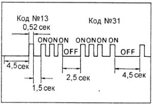
7. If two or more fault codes are stored in the memory of the electronic unit, the codes will be separated by a pause of 2.5 seconds.
8. If there are no faults, the test lamp should flash at an interval of 0.26 seconds.
– After all the codes are displayed, there is a pause of 4.5 seconds, and then they all repeat, while the “TE1” and “E1” pins of the diagnostic connector are short-circuited.
Note: in the case of several fault codes, their indication begins with a smaller code and continues ascending.
Test Mode
Note:
– On models with diagnostic connector DLC3, self-diagnosis in test mode is carried out using special testers.
– This self-test mode can be carried out on models with a diagnostic connector DLC1, without the use of special testers.
– The self-diagnostic system allows a more detailed check of the control system when the “TE2” and “E1” terminals of the diagnostic connector are bridged. This test test mode for specialists and part of the fault codes listed in the table appear only in this test mode.
– This test, in comparison with the usual one, is more sensitive (it is possible to diagnose individual circuits in real time). This is especially useful if in the process of movement there are constantly disappearing faults).
1. Verification conditions:
– engine is warmed up to operating temperature;
– the battery is fully charged (voltage not lower than 24 V);
– the throttle valve is closed (the contacts of the limit switch with the closed position of the throttle valve are closed);
– all additional equipment is turned off.
2. Turn off the ignition.
3. Put a jumper on the “TE2” and “E1” terminals of the diagnostic connector.
4. Turn on the ignition.
Note: the flashing of the lamp “CHECK ENGINE” confirms the inclusion of the test test.
5. Start the engine and drive at a speed above 5 km / h.
6. Create conditions for the failure (according to the owner).
7. After the test check, bridge the terminals “TE1” and “E1” of the diagnostic socket.
Note: “Ignition” must be turned off when bridging the leads.
8. Read the trouble codes.
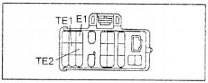
diagnostic socket
Test mode using a tester
When using the firm tester “TOYOTA” to check the engine management system in the event of a fault, a fault code is displayed. The tester is connected to the diagnostic connector “DLC3”.
Erasing trouble codes
1. Turn off the ignition.
2. Remove the fuse of the electronic control unit “ECD” or disconnect the wire from the negative terminal of the battery for one minute or more (at low temperature). On models with a DLC3 diagnostic connector, fault codes can be erased with a tester.
Note: when the battery is disconnected, the memory of other electronic devices (watches, etc.) is erased.
3. Carry out road tests of the car.
A. Repeat the diagnostic procedure and verify that there are no fault codes.
Diagnostic trouble codes of the ECU S05C, S05D
Code / Sensor or System / Status / Location of Fault
12
Crankshaft Position Sensor [TDC]
No “TDC” signal transmission to the electronic control unit at a crankshaft rotation frequency of 400 rpm or more
1. Open or short circuit in crankshaft position sensor circuit.
2. Crankshaft position sensor.
3. Electronic control unit.
13
Sensor of frequency of rotation of a shaft of TNVD [NE + NE-]
1. There is no signal transfer “NE” to the electronic control unit for 0.5 seconds at a speed of 630 rpm and above.
2. There is no “NE” signal to the electronic control unit for 2 seconds or more when the crankshaft is cranked by the starter.
1. Open or short circuit in the sensor circuit of the shaft speed sensor pump.
2. The sensor shaft speed pump.
3. Electronic control unit.
14
Solenoid valve for adjusting the injection timing [TCV]
On the warmed-up engine, the indication of the solenoid valve for adjusting the injection advance angle with the data in the memory of the electronic control unit does not match for 20 seconds.
1. Open or short circuit of the z-circuit of the solenoid valve for adjusting the injection advance angle.
2. Fuel filter (clogging).
3. Fuel freezes or air gets caught.
4. TNVD (internal pressure and solenoid valve of injection timing).
5. Electronic control unit.
19 (1)
Throttle Position Sensor [VA, VAS, E2C]
Open or short in accelerator pedal position sensor circuit for 1.0 second
and more
1. An open or short circuit in the accelerator pedal position sensor circuit.
2. Accelerator pedal position sensor.
3. Electronic control unit.
19 (2)
Throttle Position Sensor [IDL, E2C]
1. State (a) or (b) within 0.5 seconds or more:
a) Idle limit switch in the “ON ‘(IDL” ON “) position and output voltage
“VA”> 1.4 V;
b) Idle limit switch in the “ON’ (IDL “ON”) position and output voltage
“VAS”> 1.4 V.
2. State (a) or (b) lasts 0.05 seconds or more:
a) Limit switch idle in the “OFF” position (IDL “OFF”) and the voltage at the output
“VA” <0.6 V;
b) Idle limit switch in the “OFF” position (IDL “OFF”) and the voltage at the output
and “VAS” <0.6 V.
3. State (a) or (b) lasts 0.05 seconds or more:
a) 0.6 V <“VA” <4.4 V and 0.6 V <“VAS” <4.4 V;
b) “VA” – “VAS”> 0.5 V.
1. An open or short in the accelerator pedal position sensor circuit.
2. Accelerator pedal position sensor.
3. Electronic control unit.
19 (3)
Throttle Position Sensor [PDL]
State (a), (b) or (c) continues for 0.5 seconds or more:
a) Accelerator pedal pressed “ON”;
b) Voltage at pin “VA”> voltage fully closed + 0.41 V.
1. Short circuit in the circuit limit switch idle.
2. Limit switch idle.
3. Electronic control unit.
19 (4)
Throttle Position Sensor [PDL]
The signal “PDL” comes even when the car is moving.
Note: a two-stage fault finding algorithm is used.
The states (a) and (b) continue for 5 seconds or more:
a) Accelerator pedal not pressed (PDL “OFF”);
b) Holon limit switch in the “ON” position
1. Open circuit in the limit switch circuit.
2. Limit switch idle.
3. Electronic control unit.
22
Coolant temperature sensor signal [THW, E2]
An open or short in the coolant temperature sensor circuit (“THW”) for 1.0 s or more
1. Coolant temperature sensor circuit.
2. Coolant temperature sensor.
3. Electronic control unit.
25
Electropneumo Noise Suppressor Valve
An open or a short in the squelch circuit of the electropneumatic valve for 1.0 s or
more
1. Open or short circuit in the circuit of the electropneumatic valve of the noise suppressor.
2. Electronic control unit.
28
Mountain Brake Solenoid Valve
Open or short circuit in the mountain brake solenoid valve circuit for 1.0 s
or more
1. Open or short circuit in the circuit of the magnetic brake solenoid valve.
2. Electronic control unit.
32
Block of correction resistors [DATA, CLK, E2]
Circuit of correction resistors tvdd
1. An open or short in the correction resistor circuit
2. Block corrective resistors.
3. Electronic control unit.
33
Electro-damper control valve pneumatic throttle valve
Open or short in throttle control electropneumatic valve circuit
1. Open or short in throttle actuator electropneumatic circuit.
2. Electro-pneumatic valve.
3. Electronic control unit.
39
Fuel temperature sensor
A rupture or short circuit in the fuel temperature sensor circuit for 1.0 s or more
1. Open or short in fuel temperature sensor circuit.
2. Fuel temperature sensor.
3. Electronic control unit.
42
Vehicle speed sensor [SP1]
The signal does not enter the electronic control unit when the vehicle is moving for 8 or more
seconds under the following conditions:
– speed signal 0 km / h;
– crankshaft rotation speed 2400 – 4000 rpm;
– coolant temperature 60 ° C or more;
– the accelerator pedal is depressed by 29% or more.
1. Vehicle speed sensor circuit.
2. Vehicle speed sensor.
3. The instrument cluster.
4. Electronic control unit.
95
Electronic control unit
Internal error of the electronic control unit
1. Open or short in the mountain brake electric pneumatic circuit.
2. Electronic control unit.
96
Exhaust gas recirculation valve
No “EGLS” signal in ECU for 1.0 second or more
1. Open or short in exhaust gas recirculation valve circuit.
2. Position sensor for exhaust gas recirculation system.
3. Electronic control unit.
97
Electronic control unit signal
Although the “SPVD” signal comes from the electronic control unit at a frequency
rotation of the engine 500 rpm and higher, the signal “SPVF” does not flow to the electronic control unit in
for 5 times or more
1. Open or short circuit in the electronic control unit circuit.
2. Electronic control unit.
3. Electromagnetic relief valve.
Diagnostic trouble codes of ECU S05C-TB
12
Engine Speed Sensor [TDC or G1J
No signal “G1” in the presence of the signal “NE” at 3600 rpm
1. Open or short circuit of the camshaft position sensor circuit.
2. The camshaft position sensor.
3. Camshaft pulley.
4. Electronic control unit.
13
Sensor of frequency of rotation of a shaft of TNVD [NE + NE-]
There is no signal “NE” when rotating dv-j signal “G l” at 525 rpm
1. Open or short in crankshaft speed sensor circuit.
2. The gauge of frequency of rotation of a cranked hall.
3. The rotor of the gauge of position of a cranked shaft.
4. Electronic control unit.
17
Electronic control unit
There is no normal signal at the output of the electronic control unit j or the central processor
Electronic control unit
19 (1)
Accelerator pedal position sensor (open / short circuit)
1. State (a) or (b) last for 0.5 seconds or more:
a) “АССР1 <or = 0.6 V;
b) “ASSR1”> or = 4.6 V.
2. State (a) or (b) last for 0.5 seconds or more:
a) “ASSR2” <or = 0.6 V;
b) “ASSR2”> or = 4.6 V.
1. An open or short in the accelerator pedal position sensor circuit.
2. Accelerator pedal position sensor.
3. Electronic control unit.
19 (2)
Accelerator pedal position sensor
1. There is a place to be any of the following states:
a) The engine is idling (ACC off);
b) There is no incorrect voltage on the sensor No. 1 or No. 2;
c) 0.65 V <or = “ASSR2” <or = 1.05 V;
d) “ASSR1”> or = 1.5 V.
2. There is a place to be any of the following states:
a) The engine is idling (ACC off);
b) There is no wrong voltage on the sensor number 1 or number 2;
c) 0.65 V <or = “ASSR2” <or = 1.05 V;
d) “ASSR2”> or = 1.5 V.
1. An open or short in the accelerator pedal position sensor circuit.
2. Accelerator pedal position sensor.
3. Electronic control unit.
19 (3)
Accelerator pedal limit switch (short circuit)
Short circuit in the accelerator pedal limit switch
1. Short circuit in the limit switch circuit.
2. Accelerator pedal position sensor.
3. Electronic control unit.
19 (4)
Accelerator pedal limit switch (open)
Rupture in the accelerator pedal switch
1. Open circuit in the limit switch.
2. Accelerator pedal position sensor.
3. Electronic control unit.
22
Coolant Temperature Sensor Signal
Open or short in coolant temperature sensor circuit for 3.0 s
or more
1. Chain Danica Coolant Temperature.
2. Coolant temperature sensor.
3. Electronic control unit.
28
Mountain Brake Solenoid Valve
Open or short circuit in the mountain brake solenoid valve circuit for 1.0 s
or more
1. Open or short circuit in the circuit of the magnetic brake solenoid valve.
2. Mountain brake system.
3. Electronic control unit.
32
Block Correction Resistors
Circuit of correction resistors tvdd
1. An open or short in the correction resistor circuit.
2. Block corrective resistors.
3. Electronic control unit.
35
Boost pressure sensor
Open or short in boost pressure sensor circuit for 1.0 s or more
1. An open or a short in the charge pressure sensor circuit or in the electric pneumatic valve circuit.
2. Boost pressure sensor.
3. Electric pneumatic valve.
4. Turbocharging system.
5. Electronic control unit.
39
Fuel temperature sensor
Open or short in fuel temperature sensor circuit for 3.0 s or more
1. Open or short in fuel temperature sensor circuit.
2. Fuel temperature sensor.
3. Electronic control unit.
42
Vehicle Speed Sensor [SPD]
The signal does not enter the electronic control unit when the vehicle is moving at a speed of 30 km / h under the following conditions:
a) speed signal 0 km / h;
b) crankshaft rotation speed of 2400 – 4000 rpm;
c) coolant temperature 60 ° C or more;
d) the accelerator pedal is depressed by 29% or more.
1. Vehicle speed sensor circuit.
2. Vehicle speed sensor.
3. The instrument cluster.
4. Electronic control unit.
49/83
Pressure sensor in the system “Common Rail”
Open or short in Common Rail pressure transducer
1. An open or a short in the common rail pressure sensor.
2. Fuel pressure sensor in the system “Common Rail”.
3. Electronic control unit.
78 (1)
Fault in the Common Rail fuel line
States “a”, “b” and “c” are determined in the absence of fault codes 78 (2), (3), 49 and 83, frequency
engine rotation over 650 rpm and coolant temperature over 60 ° C:
a) when determining the fault code 81, the design pressure is 5 MPa less than the required one;
b) when the difference between the calculated pressure and the required about 5 MPa at idle,
the power supply of the pump is higher than usual at idle, and this condition continues for some time;
c) when the injection volume is 0 and the difference between the design pressure and the required pressure is about 5 MPa, the injection pump power supply is greater, and this condition continues for some time.
1. Leaks in the fuel line.
2. Blockage in the fuel supply line.
3. fuel pump.
78 (2)
Malfunction in the fuel pump system (short circuit)
Short circuit in PCV2 circuit
1. Short circuit in PCV2.
2. Fuel supply control valve (built into the fuel injection pump).
3. Electronic control unit.
78 (3)
Malfunction in the fuel pump system (high pressure)
The change in pressure of the “Common Rail” system does not correspond to the change in pressure of the fuel supply
pump
1. Open or short in fuel pressure sensor circuit.
2. Fuel pressure sensor.
3. Engine speed sensor.
4. Fuel pump.
5. The angle of advance of injection.
6. Electronic control unit.
78 (4)
Malfunction in the fuel pump system (short circuit)
Short circuit in the PCV1 circuit
1. Short circuit in PCV1.
2. Fuel supply control valve (built into the fuel injection pump).
3. Electronic control unit.
79 (1)
79 (2)
79 (3)
79 (4)
Error control system of fuel supply to cylinders (cylinder number 1, number 2, number 3 or number 4)
The difference in the compensation of the volume of fuel (cylinder number 1, number 2, number 3 or number 4)
1. Fuel tube from the common line to the nozzle).
2. The nozzle.
3. Damper (on a common highway).
4. Electronic control unit
81
Malfunction of the fuel pump system (no pressure / pressure limiter tripped)
Maximum pressure in the Common Rail system is maintained when there are no DTCs.
78 (2), (4) and 83
1. Safety valve (on “Common Rail”).
2. fuel pump.
82
Engine spacing
Engine speed 3900 rpm and above
1. The camshaft position sensor.
2. Crankshaft position sensor.
3. Electronic control unit.
84
Malfunction in Common Rail system (pressure does not change)
Does not change the pressure in the system “Common Rail” when the engine is running
1. Fuel pressure sensor circuit.
2. Fuel pressure sensor.
3. Electronic control unit.
85
Relief Valve Relay (PCV)
Malfunction in overflow valve (PCV) relay circuit
1. Open or short in overflow valve relay circuit.
2. Overflow valve relay.
3. Electronic control unit.
86 (1)
86 (2)
86 (3)
86 (4)
Nozzle 1 malfunction, no. 2, no. 3, or no. 4
Break in a chain of a nozzle No. 1, No. 2, No. 3 or No. 4
1. Open or short in injector circuit.
2. The nozzle.
3. Posting.
4. Electronic control unit.
86 (5) / 86 (6)
Injector malfunction (short circuit)
Short circuit in the “+ B” or “GND” nozzles
1. Open or short in injector circuit.
2. The nozzle number 1.
3. The nozzle number 2.
4. Electronic control unit.
92
Engine Stop Switch Malfunction
Engine stop switch
1. Open or short in the engine stop switch circuit.
2. Engine stop switch.
3. Posting.
4. Electronic control unit.

hi I am looking for a hino J07E engine workshop manual
R/Dear!
Plz send me Hino Truck engine and gearbox codebook in pdf thanks