International Trucks Fault Codes List (DTCs) for Model: 3200, 4100, 4300, 4400, 7300, 7400, 7500, 7600, 7700, 8500, 8600,
BE 200, CE Bus, CXT, DuraStar, LoneStar, MXT, ProStar, RXT, TranStar, WorkStar
See also: International Trucks Service Repair Manuals PDF

International 8600
Fault codes in PDF
International 3200, 4100, 4300, 4400, 7300, 7400, 7500, 7600, 7700, 8500, 8600 fault code list (PDF) – download
DISPLAYING DIAGNOSTIC TROUBLE CODES
The ability to display diagnostic trouble codes (DTC) is an optional feature. Codes may be displayed on either the gauge cluster or an optional vehicle information display (VID). The vehicle must be equipped with the option to display codes in both cases. Codes will not be displayed on the gauge cluster if the vehicle is equipped with the VID.
VEHICLES EQUIPPED WITH OPTION TO DISPLAY CODES
Displaying Codes on the Gauge Cluster (Non-VID equipped vehicles)
To display codes on vehicles not equipped with a VID:
- Set the parking brake.
- Turn the key switch to the ACCESSORY position to view only previously active codes. Turn the key switch to the IGNITION position to view both active and previously active codes.
- Momentarily press the Cruise “ON” switch and the Cruise “Resume” switch at the same time.
A gauge sweep will be performed on the gauges. The gauge cluster will then display the following information for 5 seconds:
- Software Rev: XXX
- Hardware Rev: XXX
- Active Faults: XXX
- Total Faults: XXX
NOTE – The gauge cluster will only display “Software Rev” and “Hardware Rev” for 5 seconds followed by the message “Diagnostic Trouble Codes are not available” if the vehicle is not equipped with the option to display codes.
If faults are present, the gauge cluster display will show each diagnostic trouble code for 10 seconds and then automatically scroll to the next entry and continue to cycle through the faults. Once all faults have been displayed the number of faults will be displayed again, then the cycle will repeat. To manually cycle through the fault list press and release the cluster display selector button. The following information will be displayed for each fault:
SPN: XXXX FMI: XX
Active
OC: XXX SA: XXX
SPN: XXXX FMI: XX
Previously Active OC: XXX SA: XXX
NOTE – Turning the key switch off, turning the key switch to the CRANK position, or releasing the park brake will take the gauge cluster out of the diagnostic mode.
Displaying Codes on the VID (if equipped)
The VID can be used to display all diagnostic trouble codes (DTC) on the vehicle. Suspect parameter number (SPN), failure mode indicator (FMI) and occurrence count numbers are listed. Source addresses and DTC descriptions are presented in plain text.
NOTE – The VID will display “Not Available” if a DTC description is not available for a particular fault.
Displaying codes will only be allowed if all of the following conditions are true:
• The key switch is in the IGNITION position.
• AND displaying codes is allowed due to vehicle orderable options
• AND the programmable parameter “Diagnostics” is enabled using Diamond Logic® Builder (DLB).
• The vehicle is not moving (the Vehicle Speed is equal to zero).
• The feature is not password protected to prevent unauthorized access. Refer to the Vehicle Information Display Owner’s Manual for more information.
Perform the following steps if all of the above conditions are met:
1. Go to the main menu screen
NOTE – The following selections will not be available if the vehicle is not equipped with the option to display codes.
2. Select “DIAGNOSTIC CODES”
3. Select “ACTIVE” or “INACTIVE”. The VID may initiate a password prompt if the VID has been password protected. Refer to the Vehicle Information Display Owner’s Manual for more information.
The VID will indicate “NO FAULT DETECTED” if faults are not found. Scroll through the list of faults if faults are present.
The following information will be displayed for each fault: SPN : FMI OC
SA
DTC Description
CLEARING DIAGNOSTIC TROUBLE CODES
Previously active diagnostic trouble codes can only be cleared by a service tool, such as Diamond Logic® Builder (DLB). Some previously active codes may not be cleared by this method.
DEFINITIONS
- “SPN” represents the Suspect Parameter Number. This number identif es the item for which diagnostics are being reported.
- FMI” is the Failure Mode Indicator. This number represents the type of failure detected. Refer to Failure Mode Indicators (FMI) below for more information.
- Active” or “Previously Active” will be displayed to identify whether a fault is currently active or if the fault was previously active.
- OC” is the Occurrence Count. This number represents the number of times a fault has gone from previously active to active.
- “SA” is the Source Address. This number identif es the module reporting the fault. Refer to Source Addresses (SA) for more information.
FAILURE MODE INDICATORS (FMI)
FMI=0 – Data Valid But Above Normal Operational Range – Most Severe Level
FMI=1 – Data Valid But Below Normal Operational Range – Most Severe Level
FMI=2 – Data Erratic, Intermittent Or Incorrect
FMI=3 – Voltage Above Normal, Or Shorted To High Source
FMI=4 – Voltage Below Normal, Or Shorted To Low Source
FMI=5 – Current Below Normal Or Open Circuit
FMI=6 – Current Above Normal Or Grounded Circuit
FMI=7 – Mechanical System Not Responding Or Out Of Adjustment
FMI=8 – Abnormal Frequency Or Pulse Width Or Period
FMI=9 – Abnormal Update Rate
FMI=10 – Abnormal Rate Of Change
FMI=11 – Root Cause Not Known
FMI=12 – Bad Intelligent Device Or Component
FMI=13 – Out Of Calibration
FMI=14 – Special Instructions
FMI=15 – Data Valid But Above Normal Operating Range – Least Severe Level
FMI=16 – Data Valid But Above Normal Operating Range – Moderately Severe Level
FMI=17 – Data Valid But Below Normal Operating Range – Least Severe Level
FMI=18 – Data Valid But Below Normal Operating Range – Moderately Severe Level
FMI=19 – Received Network Data In Error
FMI=20 – Data Drifted High
FMI=21 – Data Drifted Low
FMI=31 – Condition Exists
SOURCE ADDRESSES (SA)
NOTE – The available source addresses will vary depending on each vehicle configuration.
NOTE – Diagnostic Trouble Codes listed in this document are Body Controller, Auxiliary Gauge Switch Pack, Secondary Instrument Cluster, Instrument Cluster, Rear HVAC Module, and Compass Module.
DIAGNOSTIC TROUBLE CODE (DTC) LIST
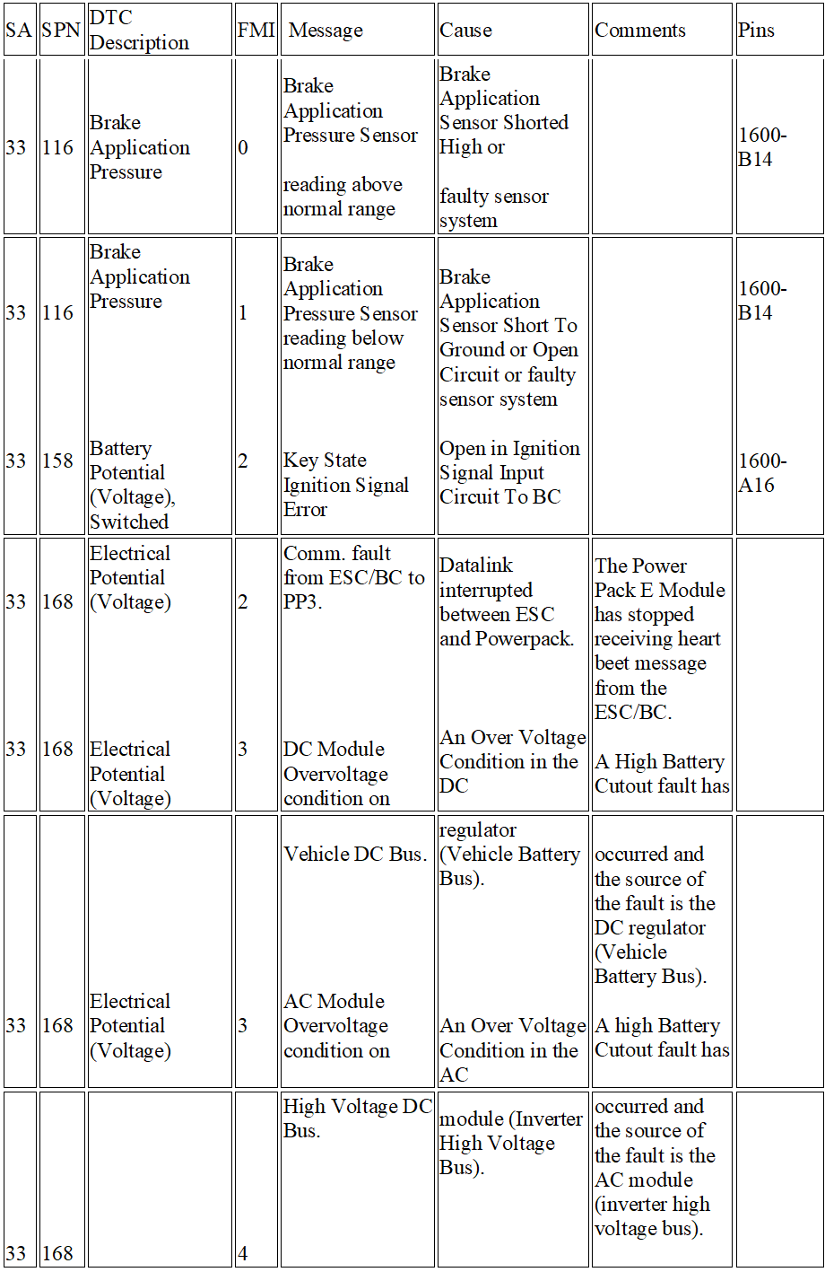
| SA | SPN | DTC Description | FMI | Message | Cause | Comments | Pins |
| 33 | 116 | Brake Application Pressure | 0 | Brake Application Pressure Sensor
reading above normal range |
Brake Application Sensor Shorted High or
faulty sensor system |
1600-B14 | |
| 33
33 |
116
158 |
Brake Application Pressure
Battery Potential (Voltage), Switched |
1
2 |
Brake Application Pressure Sensor reading below normal range
Key State Ignition Signal Error |
Brake Application Sensor Short To Ground or Open Circuit or faulty sensor system
Open in Ignition Signal Input Circuit To BC |
1600-B14
1600-A16 |
|
| 33
33 |
168
168 |
Electrical Potential (Voltage)
Electrical Potential (Voltage) |
2
3 |
Comm. fault from ESC/BC to PP3.
DC Module Overvoltage condition on |
Datalink interrupted between ESC and Powerpack.
An Over Voltage Condition in the DC |
The Power Pack E Module has stopped receiving heart beet message from the ESC/BC.
A High Battery Cutout fault has |
|
|
33 |
168 |
Electrical Potential (Voltage) |
3 |
Vehicle DC Bus.
AC Module Overvoltage condition on |
regulator (Vehicle Battery Bus).
An Over Voltage Condition in the AC |
occurred and the source of the fault is the DC regulator (Vehicle Battery Bus).
A high Battery Cutout fault has |
|
|
33 |
168 |
Electrical Potential (Voltage) |
4 |
High Voltage DC Bus.
DC Module Undervoltage condition |
module (Inverter High Voltage Bus).
An Under Voltage Condition in the DC |
occurred and the source of the fault is the AC module (inverter high voltage bus).
A Low Battery Cutout fault has |
|
|
33 |
168 |
Electrical Potential (Voltage) |
4 |
on Vehicle DC Bus.
AC Module Undervoltage condition |
regulator (Vehicle Battery Bus).
An Under Voltage Condition in the AC |
occurred and the source of the fault is the DC regulator (Vehicle Battery Bus).
A low Battery Cutout fault has |
|
|
33 |
168 |
Electrical Potential (Voltage) |
6 |
on High Voltage DC Bus.
AC Module has shutdown due to |
module (Inverter High Voltage Bus).
A Surge may have occurred for a while in |
occurred and the source of the fault is the AC module (inverter high voltage bus).
An Overload condition has been |
|
|
33 |
168 |
Electrical Potential (Voltage) |
8 |
overload condition.
Phase missing fault/alternator fault. |
the Vehicle AC bus for a long time (The inverter supplies additional current to the load).
One or more of the three phase wire from |
detected in the AC module and the Vehicle AC bus is shutdown.
One or more of the three phase |
|
|
33 |
168 |
Electrical Potential (Voltage) |
16 |
DC module over temperature |
the Dynamic Alternator to the Power Pack E module may be disconnected.
An overcurrent condition in the Vehicle DC |
wires from the alternator is disconnected. The Power Pack system is shutdown and requires an ignition cycle.
An Over Temperature fault has |
|
|
33 |
168 |
Electrical Potential (Voltage) |
16 |
condition.
AC module over temperature |
Bus might have caused an over temperature.
An overcurrent condition in the Vehicle AC |
occurred and the source of the fault is the DC regulator (Vehicle Battery Bus).
An Over temperature fault has |
|
|
33 |
168 |
Electrical Potential (Voltage) |
17 |
condition.
PPE3 Fuse Open. |
Bus might have caused an over temperature.
Load exceeded rating. |
occurred and the source of the fault is the AC module (inverter high voltage bus).
PPE3 module Fuse is Open. |
|
| 33
33 |
175
175 |
Engine Oil Temperature 1
Engine Oil Temperature 1 |
0
1 |
Engine Oil Temp Sensor reading above normal range
Engine Oil Temp Sensor reading |
Engine Oil Temperature Sensor Shorted High or Open Circuit or faulty sensor system
Engine Oil Temperature Sensor Short to |
1600-B6
1600-B6 |
|
|
33 |
177 |
Transmission Oil Temperature |
0 |
below normal range
Transmission Oil Temperature |
Ground or faulty sensor system
Transmission Oil Temperature Sensor |
1600-B7 |
|
|
33 |
177 |
Transmission Oil Temperature |
1 |
Sensor reading above normal range
Transmission Oil Temperature |
Shorted High or Open Circuit or faulty sensor system
Transmission Oil Temperature Sensor |
1600-B7 |
|
| Sensor reading below normal range | Short to Ground or faulty sensor system | ||||||
| 33
33 |
247
564 |
Total Engine Hours
Differential Lock State – Central |
9
5 |
Engine Total Hours Not Received
Transfer Case Lock Under Current |
The Engine Control Module did send the Total Engine Hours or possible Data Link failure
Current below normal or open circuit |
Not available |
Not |
|
33 |
564 |
Differential Lock State – Central |
6 |
Or Open Circuit
Transfer Case Lock Relay Over |
Current above normal or grounded circuit |
Not available |
available
Not |
|
33 |
566 |
Differential Lock State – Central Rear |
5 |
Current
Power Divider Lock Relay Under |
Open Circuit in Power Divider Lock Circuit |
available | |
|
33 |
566 |
Differential Lock State – Central Rear |
6 |
Current Or Open Circuit
Power Divider Lock Relay Over |
Short To Ground in Power Divider Lock |
||
|
33 |
567 |
Differential Lock State – Front Axle 1 |
5 |
Current
Forward Axle 1 Diff lock air solenoid |
Circuit
Current below normal or open circuit |
Not available |
Not |
|
33 |
567 |
Differential Lock State – Front Axle 1 |
6 |
output undercurrent or open circuit
Forward Axle 1 Diff lock air solenoid |
Current above normal or grounded circuit |
Not available |
available
Not |
|
33 |
569 |
Differential Lock State – Rear Axle 1 |
5 |
output overcurrent
Forward Rear Diff Lock Relay Under |
Open Circuit in Forward Rear Diff Lock |
available | |
| Current Or Open Circuit | Circuit | ||||||
| 33 | 569 | Differential Lock State – Rear Axle 1 | 6 | Forward Rear Diff Lock Relay Over Current | Short To Ground in Forward Rear Diff Lock Circuit | ||
| 33
33 |
570
570 |
Differential Lock State – Rear Axle 2
Differential Lock State – Rear Axle 2 |
5
6 |
Rear Rear Diff Lock Relay Under Current Or Open Circuit
Rear Rear Diff Lock Relay Over |
Open Circuit in Rear Rear Diff Lock Circuit
Short To Ground in Rear Rear Diff Lock |
||
|
33 |
571 |
Retarder Enable – Brake Assist |
2 |
Current
Retarder Enable – Brake Assist |
Circuit
Data erratic, intermittent or incorrect |
||
|
33 |
576 |
Switch
ASR Off-road Switch |
2 |
On/Off switch failure
Traction Disable panel mounted |
Data erratic, intermittent or incorrect |
||
|
33 |
577 |
ASR “Hill Holder” Switch |
2 |
switch is in an invalid position
HSA Disable Switch error |
Fault in HSA Disable Switch |
Not available |
Not |
|
33 |
596 |
Cruise Control Enable Switch |
0 |
Cruise Control Switch reading above |
Shorted High or Open in Cruise Control |
available
1600-B16 |
|
|
33 |
596 |
Cruise Control Enable Switch |
1 |
normal range
Cruise Control Switch reading below |
Switches Circuit
Short To Ground in Cruise Control |
1600-B16 |
|
| normal range | Switches Circuit |
| 33 | 1837 | Convoy Driving Lamp Select | 6 | BO Drive Overcurrent | Current above normal or grounded circuit Not available |
| 33 | 1840 | Rear Black Out Marker Select | 6 | BO Marker Overcurrent | Current above normal or grounded circuit Not available |
| 33 | 1841 | Black Out Brake/Stop Lamp Select | 6 | BO Stop Overcurrent | Current above normal or grounded circuit Not available |
| 33
33 |
2000
2000 |
Source Address 0
Source Address 0 |
9
19 |
ECM Data Link Comm. Failure
PTC1 (PGN 64892) not Received |
Faulty ECM or Drivetrain Data Link
ECM not Programmed for Aftertreatment, |
| from Engine | Faulty ECM, or Faulty Drivetrain Data Link | ||||
| 33
33 |
2003
2011 |
Source Address 3
Source Address 11 |
9
9 |
TCM Data Link Comm. Failure
ABS Data Link Comm. Failure |
Faulty TCM or Drivetrain Data Link
Faulty ABS Module or Drivetrain Data Link |
|
33 |
2023 |
Gauge Cluster |
9 |
EGC Data Link Comm. Failure |
Faulty EGC or Drivetrain Data Link |
|
33 |
2040 |
Auxiliary Switch Pack #1 |
9 |
AGSP #1 Data Link Comm. Failure |
Abnormal update rate |
|
33 |
2058 |
Source Address 58 |
9 |
Rear HVAC Data Link |
Faulty Rear HVAC or Body Builder Data |
|
33 |
2058 |
Source Address 58 |
14 |
Communication Failure
Rear HVAC Data Link |
Link
Faulty Rear HVAC or Body Builder Data |
|
33 |
2062 |
Source Address 62 |
9 |
Communication Failure
Meritor Wabco Brake Controller Data |
Link
Faulty Meritor Wabco Brake Controller Not available |
|
33 |
2225 |
Remote Power Module #1 Fuse |
9 |
Link Comm. Failure to BC
RPM #1 Data Link Comm. Failure |
Module Data Link
Abnormal update rate |
|
33 |
2225 |
Remote Power Module #1 Fuse |
14 |
Remote Power Module #1 (address |
Drivetrain J1939 data link, an improperly |
| 225) has an address problem. | addressed RPM module, or a missing RPM module that the BC is expecting | ||||
| 33
33 |
2226
2226 |
Remote Power Module #2 Fuse
Remote Power Module #2 Fuse |
9
14 |
RPM #2 Data Link Comm. Failure
Remote Power Module #2 (address |
Abnormal update rate
Drivetrain J1939 data link, an improperly |
| 226) has an address problem. | addressed RPM module, or a missing RPM module that the BC is expecting | ||||
| 33
33 |
2227
2227 |
Source Address 227
Source Address 227 |
9
14 |
RPM #3 Data Link Comm. Failure
Remote Power Module #3 (address |
Abnormal update rate
Drivetrain J1939 data link, an improperly |
| 227) has an address problem. | addressed RPM module, or a missing RPM module that the BC is expecting | ||||
| 33
33 |
2228
2228 |
Remote Power Module #4 Fuse
Remote Power Module #4 Fuse |
9
14 |
RPM #4 Data Link Comm. Failure
Remote Power Module #4 (address |
Abnormal update rate
Drivetrain J1939 data link, an improperly |
| 228) has an address problem. | addressed RPM module, or a missing RPM module that the BC is expecting | ||||
| 33
33 |
2229
2229 |
Source Address 229
Source Address 229 |
9
14 |
RPM #5 Data Link Comm. Failure
Remote Power Module #5 (address |
Abnormal update rate
Drivetrain J1939 data link, an improperly |
| 229) has an address problem. | addressed RPM module, or a missing RPM module that the BC is expecting | ||||
| 33
33 |
2230
2230 |
Source Address 230
Source Address 230 |
9
14 |
RPM #6 Data Link Comm. Failure
Remote Power Module #6 (address |
Abnormal update rate
Drivetrain J1939 data link, an improperly |
| 230) has an address problem. | addressed RPM module, or a missing RPM module that the BC is expecting | ||||
| 33
33 |
2231
2231 |
Remote Power Module #7 Fuse
Remote Power Module #7 Fuse |
9
14 |
RPM #7 Data Link Comm. Failure
Remote Power Module #7 (address |
Abnormal update rate
Drivetrain J1939 data link, an improperly |
| 231) has an address problem. | addressed RPM module, or a missing RPM module that the BC is expecting | ||||
| 33
33 |
2233
2234 |
Source Address 233
Remote Air Solenoid #2 Fuse |
9
9 |
Rear Driver Door Pod Data Link Comm. Failure
Rear Passenger Door Pod Data Link |
Faulty Rear Driver Door Pod Module or Switch Data Link
Faulty Rear Passenger Door Pod Module |
|
33 |
2236 |
Source Address 236 |
9 |
Comm. Failure
Driver Door Pod Data Link Comm. |
or Switch Data Link
Faulty Driver Door Pod Module or Switch |
|
33 |
2237 |
Source Address 237 |
9 |
Failure
Passenger Door Pod Data Link |
Data Link
Faulty Passenger Door Pod Module or |
|
33 |
2239 |
Source Address 239 |
9 |
Comm. Failure
HCM Data Link Comm. Failure |
Switch Data Link
Faulty HCM or Drivetrain Data Link |
|
33 |
2239 |
Source Address 239 |
14 |
HCM Address Conflict |
Drivetrain J1939 data link, an improperly |
|
33 |
2247 |
Source Address 247 |
9 |
Communication fault from PP3 to |
addressed HCM, or a missing HCM that the BC is expecting
Private J1939 datalink problem (exceeded BC has failed to receive heartbeat |
|
33 |
2361 |
Tractor Rear High Mounted Work |
2 |
BC.
Work Light Switch Error |
bandwidth). message from PowerPack E module.
Faulty Switch Actuator or Microswitch for |
|
33 |
2362 |
Lights Command
Tractor Rear High Mounted Work |
5 |
Work Light Undercurrent |
Work Light Switch
Open in Work Light Circuit |
|
33 |
2362 |
Lights
Tractor Rear High Mounted Work |
6 |
Work Light Overcurrent |
Short To Ground or Overload in Work |
|
33 |
2368 |
Lights
Left Turn Signal Lights |
5 |
Left Front Turn Lamp Undercurrent |
Light Circuit
Open in Left Front Turn Signal Circuit |
| 33 | 2368 | Left Turn Signal Lights | 6 | Left Front Turn Lamp Overcurrent | Short To Ground or Overload in Left Front |
|
33 |
2370 |
Right Turn Signal Lights |
5 |
Right Front Turn Lamp Undercurrent |
Turn Signal Circuit
Open in Right Front Turn Signal Circuit |
| 33 | 2370 | Right Turn Signal Lights | 6 | Right Front Turn Lamp Overcurrent | Short To Ground or Overload in Right |
|
33 |
2372 |
Left Stop Light |
5 |
Left Rear Turn Lamp Undercurrent |
Front Turn Signal Circuit
Open in Left Rear Turn Signal Circuit |
| 33 | 2372 | Left Stop Light | 6 | Left Rear Turn Lamp Overcurrent | Short To Ground or Overload in Left Rear |
|
33 |
2374 |
Right Stop Light |
5 |
Right Rear Turn Lamp Undercurrent |
Turn Signal Circuit
Open in Right Rear Turn Signal Circuit |
| 33 | 2374 | Right Stop Light | 6 | Right Rear Turn Lamp Overcurrent | Short To Ground or Overload in Right |
| 33
33 |
881
881 |
Right Turn Lamp Circuit (Green)
Right Turn Lamp Circuit (Green) |
5
6 |
Trailer Right Turn Lamp Relay Under
Current Or Open Circuit Trailer Right Turn Lamp Relay Over |
Open Circuit in Trailer Right Turn Lamp
Circuit Short To Ground in Trailer Right Turn |
1601-E15
1601-E15 |
|
33 |
882 |
Tail Lamp/License Plate Lamp |
5 |
Current
Trailer License Plate Lamp Relay |
Lamp Circuit
Open Circuit in Trailer License Plate |
1601-E10 |
|
33 |
882 |
Circuit (Brown)
Tail Lamp/License Plate Lamp |
6 |
Under Current Or Open Circuit
Trailer License Plate Lamp Relay |
Lamp Circuit
Short To Ground in Trailer License Plate |
1601-E10 |
|
33 |
973 |
Circuit (Brown)
Engine Retarder Selection |
2 |
Over Current
Engine Retarder Level Selection |
Lamp Circuit
Faulty Switch Actuator or Microswitch for |
|
| Switch Error | Engine Retarder Level Select Switch | |||||
| 33 | 980 | PTO Enable Switch | 2 | Engine PTO Switch Error | Data erratic, intermittent or incorrect | |
| 33
33 |
986
1043 |
Requested Percent Fan Speed
Internal Sensor Voltage Supply |
2
0 |
Engine Fan Switch Error
Bias Voltage reading above normal |
Faulty Switch Actuator or Microswitch for Engine Fan Switch
Bias Voltage Circuit Shorted High |
|
|
33 |
1043 |
Internal Sensor Voltage Supply |
1 |
range
Bias Voltage reading below normal |
Short To Ground in Bias Voltage Circuit |
|
|
33 |
1079 |
Vref Sensor Supply Voltage |
0 |
range
5V Sensor Supply Above Normal |
Data valid but above normal operational |
|
|
33 |
1079 |
Vref Sensor Supply Voltage |
1 |
Range
5V Sensor Supply Below Normal |
range – most severe level
Data valid but below normal operational |
|
|
33 |
1081 |
Wait to Start Lamp |
4 |
Range
Wait to Start Lamp |
range – most severe level
Output shorted to ground |
|
| 33 | 1081 | Wait to Start Lamp | 6 | Wait to Start Lamp | Output overheat | |
| 33
33 |
1087
1087 |
Service Brake Air Pressure Circuit #1
Service Brake Air Pressure Circuit #1 |
0
1 |
Primary Air Tank Sensor reading above normal range
Primary Air Tank Sensor reading |
Primary Air Tank Sensor Shorted High or faulty sensor system
Primary Air Tank Sensor Short To Ground |
1600-B2
1600-B2 |
| below normal range | or Open Circuit or faulty sensor system | |||||
| 33
33 |
1088
1088 |
Service Brake Air Pressure Circuit #2
Service Brake Air Pressure Circuit #2 |
0
1 |
Secondary Air Tank Sensor reading above normal range
Secondary Air Tank Sensor reading |
Secondary Air Tank Sensor Shorted High or faulty sensor system
Secondary Air Tank Sensor Short To |
1600-B3
1600-B3 |
|
33 |
1089 |
Auxiliary Equipment Supply Pressure |
0 |
below normal range
Auxiliary Air Tank Sensor Reading |
Ground or Open Circuit or faulty sensor system
Short to High in Air Pressure Auxiliary |
1600-B2 |
|
33 |
1089 |
Auxiliary Equipment Supply Pressure |
1 |
Above Normal
Auxiliary Air Tank Sensor Reading |
Sensor Circuit
Short to Ground or Open in Air Pressure |
1600-B2 |
|
33 |
1231 |
Body Address Claim/Message |
9 |
Below Normal
J1939 Body Builder Data Link Lost |
Auxiliary Sensor Circuit
Faulty BC or Bodybuilder Data Link |
|
|
33 |
1231 |
Timeout
Body Address Claim/Message |
14 |
Global Broadcast Messages, J1939, |
||
| Timeout | proprietary, private bus (body builder) (address 255) has an unknown fault. | |||||
| 33
33 |
1238
1378 |
Traction Control Override Switch
Change Oil Lamp |
2
4 |
ATC OFF-ROAD Switch Error
Change Oil Lamp |
Faulty Switch Actuator or Micro switch for ATC OFF-ROAD Switch
Output shorted to ground |
|
| 33 | 1378 | Change Oil Lamp | 6 | Change Oil Lamp | Output overheat | |
| 33
33 |
1382
1547 |
Fuel Filter (suction side) Differential Pressure
A/C Evaporator Temperature |
14
0 |
The filter between the fuel pump and the fuel tank is plugged.
HVAC Inlet Temp Sensor reading |
Heavy build up of particulate matter in the The detection has indicated a value fuel filter preventing fuel flow. of 51 on the fuel filter signal which
indicates a severely restricted or plugged condition. HVAC Refrigerant Inlet Temperature |
1600-B5 |
|
33 |
1547 |
A/C Evaporator Temperature |
1 |
above normal range
HVAC Inlet Temp Sensor reading |
Sensor Shorted High or Open Circuit or faulty sensor system
HVAC Refrigerant Inlet Temperature |
1600-B5 |
|
33 |
1548 |
HVAC Duct Temperature |
0 |
below normal range
HVAC Outlet Temp Sensor reading |
Sensor Short To Ground or faulty sensor system
HVAC Refrigerant Outlet Temperature |
1600-B13 |
|
33 |
1548 |
HVAC Duct Temperature |
1 |
above normal range
HVAC Outlet Temp Sensor reading |
Sensor Shorted High or Open Circuit or faulty sensor system
HVAC Refrigerant Outlet Temperature |
1600-B13 |
|
33 |
1552 |
Operator Input device for Cab |
2 |
below normal range
HVAC Control Head Temperature |
Sensor Short To Ground or faulty sensor system
HVAC Motor in Wrong Position or |
|
|
33 |
1553 |
Climate Control
HVAC Blower Motor Speed |
0 |
Mix DM1
HVAC Blower Speed Analog Input |
Jammed
HVAC Blower Speed Control Shorted |
1600-B15 |
|
33 |
1553 |
Adjustment
HVAC Blower Motor Speed |
1 |
reading above normal range
HVAC Blower Speed Analog Input |
High or Open Circuit or faulty sensor system
HVAC Blower Speed Control Short To |
1600-B15 |
|
33 |
1660 |
Adjustment
Engine Automatic Start Alarm |
5 |
reading below normal range
Remote Start Alarm Buzzer Relay |
Ground or faulty sensor system
Open Circuit in Remote Start Alarm |
|
|
33 |
1660 |
Engine Automatic Start Alarm |
6 |
Under Current Or Open Circuit
Remote Start Alarm Buzzer Relay |
Buzzer Circuit
Short To Ground in Remote Start Alarm |
|
|
33 |
1709 |
Transmission Controller Power |
5 |
Over Current
PRNDL Pseudo ignition relay driver |
Buzzer Circuit
Current below normal or open circuit |
1601-E3 |
|
33 |
1709 |
Relay
Transmission Controller Power |
6 |
output Under Current Or Open Circuit
PRNDL Pseudo ignition relay driver |
Current above normal or grounded circuit |
1601-E3 |
|
33 |
1716 |
Relay
Retarder Selection, non-engine |
2 |
output overcurrent
Transmission Retarder Level |
Data erratic, intermittent or incorrect |
|
|
33 |
1741 |
Level Control Mode |
0 |
Selection Switch Failure
Mode Selection Switch Damaged or |
Data Valid but Above Normal Range, Not available |
Not |
|
33 |
1741 |
Level Control Mode |
1 |
Not Connected
Possible ECU Malfunction |
Most Severe
Data Valid, but Below Normal Range, Not available |
available
Not |
|
33 |
1747 |
Kneeling Control Mode Request |
2 |
Suspension Dump Switch Error |
Most Severe
Faulty Switch Actuator or Microswitch for |
available |
|
33 |
1755 |
Lowering Control Mode Rear Axle |
5 |
Suspension Dump Solenoid B Relay |
Suspension Dump Switch
Open Circuit in Suspension Dump |
|
| Under Current Or Open Circuit | Solenoid B Circuit | |||||
| 33
33 |
1755
1756 |
Lowering Control Mode Rear Axle
Lifting Control Mode Rear Axle |
6
5 |
Suspension Dump Solenoid B Relay Over Current
Suspension Dump Solenoid A Relay |
Short To Ground in Suspension Dump Solenoid B Circuit
Open Circuit in Suspension Dump |
|
| Under Current Or Open Circuit | Solenoid A Circuit | |||||
| 33
33 |
1756
1820 |
Lifting Control Mode Rear Axle
Ramp / Wheel Chair Lift Position |
6
5 |
Suspension Dump Solenoid A Relay Over Current
Wheelchair Lift Solenoid Relay |
Short To Ground in Suspension Dump Solenoid A Circuit
Current below normal or open circuit |
1601-E1 |
|
33 |
1820 |
Ramp / Wheel Chair Lift Position |
6 |
Under Current Or Open Circuit
Wheelchair Lift Solenoid Relay Short |
Current above normal or grounded circuit |
1601-E1 |
| To Ground |
| 33 | 2378 | Tractor Marker Light | 5 | Park Lights Undercurrent | Open in Park Lights Circuit | 1604-G | |
| 33 | 2378 | Tractor Marker Light | 6 | Park Lights Overcurrent | Short To Ground or Overload in Park | 1604-G | |
| Lights Circuit | |||||||
| 33 | 2387 | Tractor Front Fog Lights Command | 2 | Fog Light Switch Error | Faulty Switch Actuator or Microswitch for | ||
| Fog Lights Switch | |||||||
| 33 | 2388 | Fog Light 1 command | 5 | Fog Lights Relay Under Current Or | Current below normal or open circuit | 1603-F | |
| Open Circuit | |||||||
| 33 | 2388 | Fog Light 1 command | 6 | Fog Lights Relay Overcurrent | Current above normal or grounded circuit | 1603-F | |
| 33 | 2389 | Rear Fog Light Command | 2 | Rear Fog Light Switch error | Faulty Switch Actuator or Microswitch for | Not available | Not |
| Rear Fog Lights Switch | available | ||||||
| 33 | 2390 | Rear Fog Lights | 5 | Rear Fog Light Relay Under Current | Under Current Or Open Circuit in Rear | Not available | Not |
| Or Open Circuit | Fog Light Relay Driver | available | |||||
| 33 | 2390 | Rear Fog Lights | 6 | Rear Fog Lights Relay Overcurrent | Short circuit in Rear Fog Light Relay | Not available | Not |
| Driver | available | ||||||
| 33 | 2392 | Back Up Light and Alarm Horn | 5 | Reverse Lights Relay Under Current | Current below normal or open circuit | 1601-E4 | |
| Or Open Circuit | |||||||
| 33 | 2392 | Back Up Light and Alarm Horn | 6 | Reverse Lights Relay Overcurrent | Current above normal or grounded circuit | 1601-E4 | |
| 33 | 2404 | Running Light | 5 | Running Light Control relay Under | Open Circuit in Running Lights Circuit | 1601-F16 | |
| Current Or Open Circuit | |||||||
| 33 | 2404 | Running Light | 6 | Running Light Control relay Over | Short To Ground in Running Lights Circuit | 1601-F16 | |
| Current | |||||||
| 33 | 2609 | Cab A/C Refrigerant Compressor | 0 | HVAC Pressure Sensor reading | HVAC Pressure Sensor Shorted High or | 1600-B12 | |
| Outlet Pressure | above normal range | faulty sensor system | |||||
| 33 | 2609 | Cab A/C Refrigerant Compressor | 1 | HVAC Pressure Sensor reading | HVAC Pressure Short To Ground or Open | 1600-B12 | |
| Outlet Pressure | below normal range | Circuit or faulty sensor system | |||||
| 33 | 2609 | Cab A/C Refrigerant Compressor | 7 | AC – Service Now. Fan | At the current operating ambient | ||
| Outlet Pressure | Problem/Clogged Pipe | temperature the engine fan isn’t working, | |||||
| one of the AC lines has become plugged | |||||||
| or the system is over-charged. The | |||||||
| compressor is shut off to prevent damage. | |||||||
| 33 | 2609 | Cab A/C Refrigerant Compressor | 16 | HVAC High Pressure Protection | HVAC Head Pressure exceeded 480 psi. | ||
| Outlet Pressure | Compressor shut off until next key cycle | ||||||
| for system protection | |||||||
| 33 | 2636 | Windshield Wiper Motor ON/OFF | 5 | Wiper On/Off Relay Under Current | Open Circuit in Wiper On/Off Circuit | 1601-E7 | |
| Or Open Circuit | |||||||
| 33 | 2636 | Windshield Wiper Motor ON/OFF | 6 | Wiper On/Off Relay Over Current | Short To Ground in Wiper On/Off Circuit | 1601-E7 | |
| 33 | 2637 | Windshield Wiper Motor Speed | 5 | Wiper High/Low Relay Under Current | Open Circuit in Wiper High/Low Circuit | 1601-E6 | |
| Or Open Circuit | |||||||
| 33 | 2637 | Windshield Wiper Motor Speed | 6 | Wiper High/Low Relay Over Current | Short To Ground in Wiper High/Low | 1601-E6 | |
| Circuit | |||||||
| 33 | 2641 | Horn | 5 | Electric Horn Undercurrent | Open in Electric Horn Circuit | 1603-E | |
| 33 | 2641 | Horn | 6 | Electric Horn Overcurrent | Short To Ground or Overload in City Horn | 1603-E | |
| Circuit | |||||||
| 33 | 2642 | Mirror Heat 1 | 5 | Left Mirror Heat Undercurrent | Open in Left Mirror Heat Circuit | 1603-H | |
| 33 | 2642 | Mirror Heat 1 | 6 | Left Mirror Heat Overcurrent | Short to Ground or Overload in Left Mirror | 1603-H | |
| Heat Circuit | |||||||
| 33 | 2653 | Headlamp Low Beam Left #1 | 5 | Left Low Beam Under Current | Open in Left Low Beam Circuit | 1604-B | |
| 33 | 2653 | Headlamp Low Beam Left #1 | 6 | Left Low Beam Short To Ground | Short To Ground or Overload in Left Low | 1604-B | |
| Beam Circuit | |||||||
| 33 | 2655 | Headlamp Low Beam Right #1 | 5 | Right Low Beam Open Circuit | Open in Right Low Beam Circuit | 1604-H | |
| 33 | 2655 | Headlamp Low Beam Right #1 | 6 | Right Low Beam Short To Ground | Short to Ground or Overload in Right Low | 1604-H | |
| Beam Circuit | |||||||
| 33 | 2796 | Transfer Case Selector Switch | 2 | Front Axle Switch Error | Data erratic, intermittent or incorrect | ||
| 33 | 2819 | Park Interlock Error | 5 | Park Position Interlock Solenoid | Current below normal or open circuit | 1601-E8 | |
| Output is Under Current Or Open | |||||||
| Circuit. | |||||||
| 33 | 2819 | Park Interlock Error | 6 | Park Position Interlock Solenoid | Current above normal or grounded circuit | 1601-E8 | |
| Output is overcurrent. | |||||||
| 33 | 3313 | Fifth Wheel Lock Couple Status | 5 | Fifth Wheel Jaw Unlock Solenoid 1 | Open Circuit or Defective Solenoid | ||
| Indicator | output is Under Current Or Open | ||||||
| Circuit | |||||||
| 33 | 3313 | Fifth Wheel Lock Couple Status | 6 | Fifth Wheel Jaw Unlock Solenoid 1 | Short To Ground or Defective Solenoid | ||
| Indicator | output is Overcurrent | ||||||
| 33 | 3314 | Fifth Wheel Release Control | 2 | Fifth Wheel Jaw Unlock Switch state
is invalid |
Data erratic, intermittent or incorrect | ||
| 33 | 3316 | Fifth Wheel Slider Lock Indicator | 5 | Fifth Wheel Slide Under Current Or | Open Circuit in Fifth Wheel Slide Circuit | ||
| Open Circuit | |||||||
| 33 | 3316 | Fifth Wheel Slider Lock Indicator | 6 | Fifth Wheel Slide Over Current | Short To Ground in Fifth Wheel Slide | ||
| Circuit | |||||||
| 33 | 3412 | Lock Status of Door 1 | 7 | Driver Door Lock Motor Failure | Driver Door Pod Module Has Shorted, | ||
| Opened, or Jammed Solenoid | |||||||
| 33 | 3415 | Lock Status of Door 2 | 7 | Passenger Door Lock Motor Failure | Passenger Door Pod Module Has | ||
| Shorted, Opened, or Jammed Solenoid | |||||||
| 33 | 3418 | Lock Status of Door 3 | 7 | Rear Driver Door Lock Motor failure | Rear Driver Door Pod Module Has | ||
| Shorted, Opened, or Jammed Solenoid | |||||||
| 33 | 3421 | Lock Status of Door 4 | 7 | Rear Passenger Door Lock Motor | Rear Passenger Door Pod Module Has | ||
| failure | Shorted, Opened, or Jammed Solenoid | ||||||
| 33 | 3452 | Enable Switch – Transmission input | 2 | Transmission PTO A Switch Error | Faulty Switch Actuator or Microswitch for | ||
| shaft PTO 1 | Transmission PTO A Switch | ||||||
| 33 | 3452 | Enable Switch – Transmission input | 2 | PTO Engagement Switch Error | Faulty Switch Actuator or Microswitch for | ||
| shaft PTO 1 | Transmission PTO A Switch | ||||||
| 33 | 3453 | Enable Switch – Transmission input | 2 | Transmission PTO B Switch Error | Faulty Switch Actuator or Microswitch for | ||
| shaft PTO 2 | Transmission PTO B Switch | ||||||
| 33 | 3455 | Enable Switch – Transfer case output | 2 | Transfer Case Switch Error | Data erratic, intermittent or incorrect | ||
| shaft PTO | |||||||
| 33 | 3455 | Enable Switch – Transfer case output | 2 | Transfer Case PTO Switch Error | Data erratic, intermittent or incorrect | ||
| shaft PTO | |||||||
| 33 | 3456 | Engagement Consent – | 5 | Transmission PTO A Solenoid Relay | Open Circuit in Transmission PTO A | ||
| Transmission input shaft PTO 1 | Under Current Or Open Circuit | Solenoid Circuit | |||||
| 33 | 3456 | Engagement Consent – | 6 | Transmission PTO A Solenoid Relay | Short To Ground in Transmission PTO A | ||
| Transmission input shaft PTO 1 | Over Current | Solenoid Circuit | |||||
| 33 | 3457 | Engagement Consent – | 5 | Transmission PTO B Solenoid Relay | Open Circuit in Transmission PTO B | ||
| Transmission input shaft PTO 2 | Under Current Or Open Circuit | Solenoid Circuit | |||||
| 33 | 3457 | Engagement Consent – | 6 | Transmission PTO B Solenoid Relay | Short To Ground in Transmission PTO B | ||
| Transmission input shaft PTO 2 | Over Current | Solenoid Circuit | |||||
| 33
33 |
3461
3461 |
Engagement Status – Transmission
input shaft PTO 2 Engagement Status – Transmission |
5
6 |
PTO Air Solenoid Under Current Or
Open Circuit PTO Air Solenoid Overcurrent |
Current below normal or open circuit
Current above normal or grounded circuit |
|
|
33 |
3695 |
input shaft PTO 2
Regen Inhibit Switch Indicator |
2 |
Regen Inhibit Switch Error |
Faulty Switch Actuator or Microswitch for |
|
|
33 |
3696 |
Parked Regen Switch Indicator |
5 |
Open Circuit in Regen Inhibit Switch |
Regen Inhibit Switch
Open Circuit in the Regen Inhibit Switch |
|
|
33 |
3696 |
Parked Regen Switch Indicator |
6 |
Indicator Circuit.
Over current for Parked Regen |
Indicator Circuit.
Over current or Short to Battery for the |
|
|
33 |
3696 |
Parked Regen Switch Indicator |
2 |
Switch Indicator
Parked Regen Switch Error |
Parked Regen Switch Indicator.
Faulty Switch Actuator or Microswitch for |
|
|
33 |
3697 |
Particulate Trap Lamp Command |
5 |
Particulate Trap Lamp Relay Under |
Parked Regen Switch
Open Circuit in Particulate Trap Lamp |
|
|
33 |
3697 |
Particulate Trap Lamp Command |
6 |
Current Or Open Circuit
Particulate Trap Lamp Relay Over |
Circuit
Short to Ground in Particulate Trap Lamp |
|
|
33 |
3698 |
Exhaust System High Temperature |
5 |
Current
Exhaust System High Temperature |
Circuit
Open Circuit in Exhaust System High |
|
|
33 |
3698 |
Lamp Command
Exhaust System High Temperature |
6 |
Lamp Command Under Current Or Open Circuit
Exhaust System High Temperature |
Temperature Circuit
Short to Ground in Exhaust System High |
|
| Lamp Command | Lamp Command Over Current | Temperature Circuit | ||||
| 33 | 3950 | Air Horn | 5 | Air Horn Undercurrent | Open in Air Horn Circuit | 1602-E12 |
| 33 | 3950 | Air Horn | 6 | Air Horn Overcurrent | Short To Ground or Overload in Air Horn | 1602-E12 |
|
33 |
3952 |
Air Shield Light |
6 |
Air Shield Lighting Overcurrent |
Circuit
Short To Ground or Overload in Air Shield |
1604-F |
|
33 |
3957 |
Auxiliary Transmission Constant |
5 |
Auxiliary Transmission Solenoid B |
Light Circuit
Current below normal or open circuit |
|
|
33 |
3957 |
Supply Actuator
Auxiliary Transmission Constant |
6 |
(Constant Supply) output is Under Current Or Open Circuit.
Auxiliary Transmission Solenoid B |
Current above normal or grounded circuit |
|
|
33 |
3958 |
Supply Actuator
Auxiliary Transmission High Range |
5 |
(Constant Supply) output is overcurrent.
Auxiliary Transmission Solenoid C |
Current below normal or open circuit |
|
|
33 |
3958 |
Actuator
Auxiliary Transmission High Range |
6 |
(High) Output is Under Current Or Open Circuit.
Auxiliary Transmission Solenoid C |
Current above normal or grounded circuit |
|
|
33 |
3959 |
Actuator
Auxiliary Transmission Neutral |
5 |
(High) output is overcurrent.
Auxiliary Transmission Solenoid A |
Current below normal or open circuit |
|
|
33 |
3959 |
Actuator
Auxiliary Transmission Neutral |
6 |
(Neutral) output is Under Current Or Open Circuit.
Auxiliary Transmission Solenoid A |
Current above normal or grounded circuit |
|
|
33 |
3960 |
Actuator
Auxiliary Transmission Range Switch |
2 |
(Neutral) output is overcurrent.
Auxiliary Transmission High/Low |
Data erratic, intermittent or incorrect |
|
|
33 |
3961 |
Body Equipment Hydraulic Power |
5 |
Switch state is invalid.
TEM Epump Inhibit Relay Under |
Current below normal or open circuit |
1601-E1 |
|
33 |
3961 |
Auxiliary Pump Inhibit Command
Body Equipment Hydraulic Power |
6 |
Current Or Open Circuit
TEM Epump Inhibit Relay Over |
Current above normal or grounded circuit |
1601-E1 |
|
33 |
3962 |
Auxiliary Pump Inhibit Command Bus Amber Signal Light 1 |
5 |
Current
Left Front Amber PWL Undercurrent |
Current below normal or open circuit |
1603-C |
| 33 | 3962 | Bus Amber Signal Light 1 | 6 | Left Front Amber PWL Overcurrent | Current above normal or grounded circuit | 1603-C |
| 33
33 |
3963
3963 |
Bus Amber Signal Light 2
Bus Amber Signal Light 2 |
5
6 |
Right Front Amber PWL Undercurrent
Right Front Amber PWL Overcurrent |
Current below normal or open circuit
Current above normal or grounded circuit |
1604-J
1604-J |
|
33 |
3964 |
Bus Amber Signal Light 3 |
5 |
Left Rear Amber PWL Undercurrent |
Current below normal or open circuit |
1603-G |
|
33 |
3964 |
Bus Amber Signal Light 3 |
6 |
Left Rear Amber PWL Overcurrent |
Current above normal or grounded circuit |
1603-G |
|
33 |
3965 |
Bus Amber Signal Light 4 |
5 |
Right Rear Amber PWL |
Current below normal or open circuit |
1603-K |
|
33 |
3965 |
Bus Amber Signal Light 4 |
6 |
Undercurrent
Right Rear Amber PWL Overcurrent |
Current above normal or grounded circuit |
1603-K |
|
33 |
3966 |
Bus Crossing Gate |
5 |
Crossing Gate output is |
Current below normal or open circuit |
1602-E12 |
|
33 |
3966 |
Bus Crossing Gate |
6 |
undercurrent.
Crossing Gate output is overcurrent. |
Current above normal or grounded circuit |
1602-E12 |
| 33
33 |
3967
3967 |
Bus Passenger Door Close Relay
Bus Passenger Door Close Relay |
5
6 |
Bus Entrance Door Close Relay Driver Output is Under Current Or Open Circuit
Bus Entrance Door Close Relay |
Current below normal or open circuit
Current above normal or grounded circuit |
1601-E9
1601-E9 |
|
33 |
3969 |
Bus Passenger Door Control Switch |
0 |
Driver Output is overcurrent
Bus Entrance Door Steering Wheel |
Bus Door Control Switches Circuit Open |
1600-B16 |
| 2 | Switch Input Above Normal Range | or Shorted High | ||||
| 33 | 3969 | Bus Passenger Door Control Switch 2 | 1 | Bus Entrance Door Steering Wheel Switch Input Below Normal Range | Short To Ground in Bus Door Control Switches Circuit | 1600-B16 |
| 33
33 |
3970
3970 |
Bus Passenger Door Open Relay
Bus Passenger Door Open Relay |
5
6 |
Bus Entrance Door Open Relay Driver Output is Under Current Or Open Circuit
Bus Entrance Door Open Relay |
Current below normal or open circuit
Current above normal or grounded circuit |
1601-E13
1601-E13 |
|
33 |
3971 |
Bus Red Signal Light 1 |
5 |
Driver Output is overcurrent
Left Front Red PWL Undercurrent |
Current below normal or open circuit |
1603-H |
| 33 | 3971 | Bus Red Signal Light 1 | 6 | Left Front Red PWL Overcurrent | Current above normal or grounded circuit | 1603-H |
| 33 | 3972 | Bus Red Signal Light 2 | 5 | Right Front Red PWL Undercurrent | Current below normal or open circuit | 1603-F |
| 33 | 3972 | Bus Red Signal Light 2 | 6 | Right Front Red PWL Overcurrent | Current above normal or grounded circuit | 1603-F |
| 33 | 3973 | Bus Red Signal Light 3 | 5 | Left Rear Red PWL Undercurrent | Current below normal or open circuit | 1603-J |
| 33 | 3973 | Bus Red Signal Light 3 | 6 | Left Rear Red PWL Overcurrent | Current above normal or grounded circuit | 1603-J |
| 33 | 3974 | Bus Red Signal Light 4 | 5 | Right Rear Red PWL Undercurrent | Current below normal or open circuit | 1603-L |
| 33 | 3974 | Bus Red Signal Light 4 | 6 | Right Rear Red PWL Overcurrent | Current above normal or grounded circuit | 1603-L |
| 33 | 3975 | Bus Stop Arm | 5 | Bus Stop Arm Output is Under | Current below normal or open circuit | 1601-E2 |
|
33 |
3975 |
Bus Stop Arm |
6 |
Current Or Open Circuit
Bus Stop Arm Output is over current |
Current above normal or grounded circuit |
1601-E2 |
| 33 | 3976 | Cab Dome Light 1 | 5 | Cab Dome Light Open Circuit | Open in Cab Dome Light Circuit | 1604-J |
| 33 | 3976 | Cab Dome Light 1 | 6 | Cab Dome Light Short To Ground | Short To Ground or Overload in Cab | 1604-J |
| Dome Light Circuit | ||||||
| 33 | 3977 | Cab Dome Light 2 | 5 | Sleeper Dome Light Relay Under | Open Circuit in Sleeper Dome Light | 1601-F2 |
| Current Or Open Circuit | Circuit | |||||
| 33 | 3977 | Cab Dome Light 2 | 6 | Sleeper Dome Light Over Current | Short To Ground in Sleeper Dome Light | 1601-F2 |
| Circuit | ||||||
| 33 | 3978 | Cab Dome Light 2 Switch | 2 | Sleeper Dome / Floor Search Light | Faulty Switch Actuator or Microswitch for | |
| Switch Error | Sleeper Dome / Floor Search Light Switch | |||||
| 33 | 3979 | Cab Floor Light | 5 | Floor Lights Relay Under Current Or | Open Circuit in Floor Light Circuit | 1601-E5 |
| Open Circuit | ||||||
| 33 | 3979 | Cab Floor Light | 6 | Floor Lights Relay Over Current | Short To Ground in Floor Light Circuit | 1601-E5 |
| 33 | 3981 | Cab HVAC Mode Control Actuator | 2 | HVAC Control Head Mode Fault | HVAC Motor in Wrong Position or | |
| DM1 | Jammed | |||||
| 33 | 3982 | Cab HVAC Rear Blower Speed | 2 | HVAC Rear Blower Speed Control | Faulty Switch Actuator or Microswitch for | |
| Control Switch | Switch Error | HVAC Rear Blower Speed Control Switch | ||||
| 33 | 3983 | Cab HVAC Rear Temperature | 2 | Rear HVAC Temperature Control | Faulty Switch Actuator or Microswitch for | |
| Control Switch | Switch Error | Rear HVAC Temperature Control Switch | ||||
| 33 | 3984 | Cab HVAC Recirculation Door | 2 | HVAC Control Head Air Inlet DM1 | HVAC Motor in Wrong Position or | |
| Control Actuator | Jammed | |||||
| 33 | 3985 | Cab HVAC System Controller | 9 | HVAC Control Head Circuit Failed To | Abnormal update rate | |
| Communicate With the Body | ||||||
| Controller | ||||||
| 33 | 3987 | Compression Brake Enable Switch | 5 | Compression Brake Indicator output | Current below normal or open circuit | 1601-E4 |
| Indicator Lamp | is Under Current Or Open Circuit | |||||
| 33 | 3987 | Compression Brake Enable Switch | 6 | Compression Brake Indicator is over | Current above normal or grounded circuit | 1601-E4 |
| Indicator Lamp | current | |||||
| 33 | 3988 | Door 1 Control Module | 7 | Driver Door Pod Module Failure | Defective Driver Door Pod Module | |
| 33 | 3989 | Door 1 Window Motor | 7 | Driver Window Motor Failure | Driver Door Pod Module Window Motor | |
| Has Short or Open or Window is Jammed | ||||||
| 33 | 3990 | Door 2 Control Module | 7 | Passenger Door Pod Module Failure | Defective Passenger Door Pod Module | |
| 33 | 3991 | Door 2 Window Motor | 7 | Passenger Window Motor Failure | Passenger Door Pod Module Window | |
| Motor Has Short or Open or Window is | ||||||
| Jammed | ||||||
| 33 | 3992 | Door 3 Control module | 7 | Rear Driver Door Pod Module Failure | Defective Rear Driver Door Pod Module | |
| 33 | 3993 | Door 3 Window Motor | 7 | Rear Driver Window Motor Failure | Rear Driver Door Pod Module Window | |
| Motor Has Short or Open or Window is | ||||||
| Jammed | ||||||
| 33 | 3994 | Door 4 Control Module | 7 | Rear Passenger Door Pod Module | Defective Rear Passenger Door Pod | |
| Failure | Module | |||||
| 33 | 3995 | Door 4 Window Motor | 7 | Rear Passenger Window Motor | Rear Passenger Door Pod Module | |
| Failure | Window Motor Has Short or Open or | |||||
| Window is Jammed | ||||||
| 33 | 3997 | Electrical Accessory Power Relay | 5 | Electrical Accessory Request Relay | Open Circuit in Electrical Accessory | 1601-E11 |
| Under Current Or Open Circuit | Request Circuit | |||||
| 33 | 3997 | Electrical Accessory Power Relay | 6 | Electrical Accessory Request Relay | Short To Ground in Electrical Accessory | 1601-E11 |
| Over Current | Request Circuit | |||||
| 33 | 3998 | Electrical Load Shed OFF | 5 | Load Shed OFF Relay Under | Open Circuit in Load Shed OFF Circuit | 1601-F7 |
| Current Or Open Circuit | ||||||
| 33 | 3998 | Electrical Load Shed OFF | 6 | Load Shed OFF Relay Over Current | Short To Ground in Load Shed OFF | 1601-F7 |
| Circuit | ||||||
| 33 | 3999 | Electrical Load Shed ON | 5 | Load Shed ON Relay Under Current | Open Circuit in Load Shed ON Circuit | 1601-F6 |
| Or Open Circuit | ||||||
| 33 | 3999 | Electrical Load Shed ON | 6 | Load Shed ON Relay Over Current | Short To Ground in Load Shed ON Circuit | 1601-F6 |
| 33 | 4002 | Engine Remote Start | 6 | TEM Engine Crank Relay Over | Current above normal or grounded circuit | |
| Current | ||||||
| 33 | 4003 | Engine Remote Stop | 5 | TEM Engine Stop Relay Under | Current below normal or open circuit | 1601-E2 |
| Current Or Open Circuit | ||||||
| 33 | 4003 | Engine Remote Stop | 6 | TEM Engine Stop Relay Over | Current above normal or grounded circuit | 1601-E2 |
| Current | ||||||
| 33 | 4004 | Exterior Lamp Check Switch | 2 | Exterior Lamp Check Switch Error | Data erratic, intermittent or incorrect | |
| 33 | 4007 | Fifth Wheel Slide Lock Switch | 2 | Fifth Wheel Slide Switch Error | Faulty Switch Actuator or Microswitch for | |
| Fifth Wheel Slide Switch | ||||||
| 33 | 4008 | Fog Light 2 | 5 | Right Fog Light Undercurrent | Open in Right Fog Light Circuit | 1603-K |
| 33 | 4008 | Fog Light 2 | 6 | Right Fog Light Overcurrent | Short To Ground or Overload in Right Fog | 1603-K |
| Light Output Circuit | ||||||
| 33 | 4009 | Fuel Filter Fuel Heater Relay | 5 | Fuel Heater Relay Under Current Or | Open Circuit in Fuel Heater Circuit | 1601-F12 |
| Open Circuit | ||||||
| 33 | 4009 | Fuel Filter Fuel Heater Relay | 6 | Fuel Heater Relay Over Current | Short To Ground in Fuel Heater Circuit | 1601-F12 |
| 33 | 4010 | Fuel Tank Transfer Pump | 5 | Fuel Transfer Pump Relay Under | Open Circuit in Fuel Transfer Pump | 1601-F11 |
| Current Or Open Circuit | Circuit | |||||
| 33 | 4010 | Fuel Tank Transfer Pump | 6 | Fuel Transfer Pump Relay Short To | Short To Ground in Fuel Transfer Pump | 1601-F11 |
| Ground | Circuit | |||||
| 33 | 4011 | Headlamp 1 High Beam | 5 | Left High Beam Open Circuit | Open in Left High Beam Circuit | 1604-C |
| 33 | 4011 | Headlamp 1 High Beam | 6 | Left High Beam Short To Ground | Short To Ground or Overload in Left High | 1604-C |
| Beam Circuit | ||||||
| 33 | 4012 | Headlamp 2 High Beam | 5 | Right High Beam Open Circuit | Open in Right High Beam Circuit | 1604-K |
| 33 | 4012 | Headlamp 2 High Beam | 6 | Right High Beam Short To Ground | Short To Ground or Overload in Right | 1604-K |
| High Beam Circuit | ||||||
| 33 | 4014 | High Current Auxiliary Load Switch 1 | 2 | High Current Load Switch Error | Data erratic, intermittent or incorrect | |
| 33 | 4016 | High Current Auxiliary Power Relay 1 | 5 | High Current Load Under Current Or | Current below normal or open circuit | 1601-E16 |
| Open Circuit | ||||||
| 33 | 4016 | High Current Auxiliary Power Relay 1 | 6 | High Current Load Overcurrent | Current above normal or grounded circuit | 1601-E16 |
| 33 | 4022 | Lift Gate Power Control Enable | 5 | Lift Gate Enable Undercurrent | Current below normal or open circuit | 1603-J |
| 33 | 4022 | Lift Gate Power Control Enable | 6 | Lift Gate Enable Overcurrent | Current above normal or grounded circuit | 1603-J |
| 33 | 4023 | Lift Gate Power Control Switch | 2 | Lift Gate Switch Error | Data erratic, intermittent or incorrect | |
| 33 | 4024 | Marker Light Interrupt Switch | 2 | Marker Light Interrupt Switch Failure | Data erratic, intermittent or incorrect |
| 33 | 4026 | Mirror Heat 2 | 5 | Right Mirror Heat Undercurrent | Open in Right Mirror Heat Circuit | 1603-L | |
| 33 | 4026 | Mirror Heat 2 | 6 | Right Mirror Heat Overcurrent | Short To Ground or Overload in Right | 1603-L | |
| Mirror Heat Circuit | |||||||
| 33 | 4028 | Service Brake Circuit 1 Air Tank | 5 | Service Brake Circuit 1 Air Tank | Current below normal or open circuit | ||
| Drain Valve | Drain Valve Solenoid Under Current | ||||||
| Or Open Circuit | |||||||
| 33 | 4028 | Service Brake Circuit 1 Air Tank | 6 | Service Brake Circuit 1 Air Tank | Current above normal or grounded circuit | ||
| Drain Valve | Drain Valve Solenoid Short To | ||||||
| Ground | |||||||
| 33 | 4029 | Service Brake Circuit 1 Air Tank | 2 | Service Brake Circuit 1 Air Tank | Data erratic, intermittent or incorrect | ||
| Drain Valve Switch | Drain Switch Error | ||||||
| 33 | 4030 | Service Brake Circuit 2 Air Tank | 5 | Service Brake Circuit 2 Air Tank | Current below normal or open circuit | ||
| Drain Valve | Drain Valve Solenoid Under Current | ||||||
| Or Open Circuit | |||||||
| 33 | 4030 | Service Brake Circuit 2 Air Tank | 6 | Service Brake Circuit 2 Air Tank | Current above normal or grounded circuit | ||
| Drain Valve | Drain Valve Solenoid Short To | ||||||
| Ground | |||||||
| 33 | 4031 | Service Brake Supply Air Tank Drain | 5 | Service Brake Supply Air Tank Drain | Current below normal or open circuit | ||
| Valve | Valve Solenoid Under Current Or | ||||||
| Open Circuit | |||||||
| 33 | 4031 | Service Brake Supply Air Tank Drain | 6 | Service Brake Supply Air Tank Drain | Current above normal or grounded circuit | ||
| Valve | Valve Solenoid Short To Ground | ||||||
| 33 | 4032 | Service Brake Supply Air Tank Drain | 2 | Service Brake Supply Air Tank Drain | Data erratic, intermittent or incorrect | ||
| Valve Switch | Valve Switch Error | ||||||
| 33 | 4033 | Sleeper Remote – Start/Stop Enable | 5 | Sleeper Control Enable Relay Under | Current below normal or open circuit | ||
| Command | Current or Open Circuit | ||||||
| 33 | 4033 | Sleeper Remote – Start/Stop Enable | 6 | Sleeper Control Enable Relay Over | Short To Ground in Sleeper Control | ||
| Command | Current | Enable Circuit | |||||
| 33 | 4038 | Snow Plow Forward Lighting Relay 2 | 5 | Right Plow Light Relay Under | Current below normal or open circuit | 1601-F16 | |
| Current Or Open Circuit | |||||||
| 33 | 4038 | Snow Plow Forward Lighting Relay 2 | 6 | Right Plow Light Relay Circuit Short | Current above normal or grounded circuit | 1601-F16 | |
| To Ground | |||||||
| 33 | 4039 | Snow Plow Forward Lighting Relay 1 | 5 | Left Plow Light Relay Circuit Under | Current below normal or open circuit | 1601-F12 | |
| Current Or Open Circuit | |||||||
| 33 | 4039 | Snow Plow Forward Lighting Relay 1 | 6 | Left Plow Light Relay Circuit Short | Current above normal or grounded circuit | 1601-F12 | |
| To Ground | |||||||
| 33 | 4040 | Snow Plow Lighting Mode Switch | 2 | Snow Plow Switch Error | Data erratic, intermittent or incorrect | ||
| 33 | 4041 | Software Loop Time Exceeded | 14 | Software Loop Time Exceeded in the | Software Configuration Too Big | ||
| Body Controller, Internal Fault | |||||||
| 33 | 4042 | Trailer Auxiliary Power Switch | 2 | Trailer Auxiliary Power Switch Error | Faulty Switch Actuator or Microswitch for | ||
| Auxiliary Trailer Switch | |||||||
| 33 | 4043 | Transfer Case Front Driveline | 5 | Transfer Case Front Driveline | Current below normal or open circuit | ||
| Actuator | Solenoid Under Current Or Open | ||||||
| Circuit | |||||||
| 33 | 4043 | Transfer Case Front Driveline | 6 | Transfer Case Front Driveline | Current above normal or grounded circuit | ||
| Actuator | Solenoid Short To Ground | ||||||
| 33 | 4044 | Transfer Case High Range Actuator | 5 | Transfer Case High Range Solenoid | Current below normal or open circuit | ||
| Under Current Or Open Circuit | |||||||
| 33 | 4044 | Transfer Case High Range Actuator | 6 | Transfer Case High Range Solenoid | Current above normal or grounded circuit | ||
| Short To Ground | |||||||
| 33 | 4045 | Transfer Case Low Range Actuator | 5 | Transfer Case Low Range Solenoid | Current below normal or open circuit | ||
| Under Current Or Open Circuit | |||||||
| 33 | 4045 | Transfer Case Low Range Actuator | 6 | Transfer Case Low Range Solenoid | Current above normal or grounded circuit | ||
| Short To Ground | |||||||
| 33 | 4046 | Transfer Case Neutral Actuator | 5 | Transfer Case Neutral Solenoid | Current below normal or open circuit | ||
| Under Current Or Open Circuit | |||||||
| 33 | 4046 | Transfer Case Neutral Actuator | 6 | Transfer Case Neutral Solenoid | Current above normal or grounded circuit | ||
| Short To Ground | |||||||
| 33 | 4047 | Transfer Case Output Shaft PTO | 5 | Transfer Case Output Shaft PTO | Current below normal or open circuit | ||
| Actuator | Actuator Under Current Or Open | ||||||
| Circuit | |||||||
| 33 | 4047 | Transfer Case Output Shaft PTO | 6 | Transfer Case Output Shaft PTO | Current above normal or grounded circuit | ||
| Actuator | Actuator Over Current | ||||||
| 33 | 4048 | Transfer Case Range Switch | 2 | Transfer Case Range Switch Error | Data erratic, intermittent or incorrect | ||
| 33 | 4049 | Transfer Case Rear Driveline | 5 | Transfer Case Rear Driveline Relay | Current below normal or open circuit | ||
| Actuator | Under Current Or Open Circuit | ||||||
| 33 | 4049 | Transfer Case Rear Driveline | 6 | Transfer Case Rear Driveline Relay | Current above normal or grounded circuit | ||
| Actuator | Over Current | ||||||
| 33 | 4053 | Transmission Input Shaft PTO 2 | 5 | Transmission Input Shaft PTO | Current below normal or open circuit | Not available | Not |
| Actuator | Engagement Actuator Circuit Under | available | |||||
| Current Or Open Circuit | |||||||
| 33 | 4053 | Transmission Input Shaft PTO 2 | 6 | Transmission Input Shaft PTO | Current above normal or grounded circuit | Not available | Not |
| Actuator | Engagement Actuator Circuit | available | |||||
| Overcurrent | |||||||
| 33 | 4055 | Transmission Retarder Enable
Switch |
2 | Transmission Retarder On/Off switch
Failure |
Data erratic, intermittent or incorrect | ||
| 33 | 4056 | Two Speed Axle Actuator | 5 | Two Speed Axle Solenoid Relay | Current below normal or open circuit | ||
| Under Current Or Open Circuit | |||||||
| 33 | 4056 | Two Speed Axle Actuator | 6 | Two Speed Axle Solenoid Relay | Current above normal or grounded circuit | ||
| Short To Ground | |||||||
| 33 | 4057 | Wiper Motor | 5 | Wiper Motor Undercurrent | Open in Wiper Motor Circuit | 1604-A | |
| 33 | 4057 | Wiper Motor | 6 | Wiper Motor Overcurrent | Short To Ground or Overload in Wiper | 1604-A | |
| Motor Circuit | |||||||
| 33 | 4058 | Cab Dome Light 1 Switch | 2 | Cab Dome Light Switch is reporting | Faulty Switch Actuator or Microswitch for | ||
| an error. | Cab Dome Light Switch | ||||||
| 33 | 520461 | Switch 6-Pack #1 Data Link | 9 | Switch 6-Pack #1 Data Link Comm. | Faulty Switch Pack #1 or Switch Data Link | ||
| Failure | |||||||
| 33 | 520462 | Switch 6-Pack #2 Data Link | 9 | Switch 6-Pack #2 Data Link Comm. | Faulty Switch Pack #2 or Switch Data Link | ||
| Failure | |||||||
| 33 | 520463 | Switch 6-Pack #3 Data Link | 9 | Switch 6-Pack #3 Data Link Comm. | Faulty Switch Pack #3 or Switch Data Link | ||
| Failure | |||||||
| 33 | 520464 | Electrical Accessory Request | 5 | Electrical Accessory Request Relay
Under Current Or Open Circuit |
Open Circuit in Electrical Accessory
Request Circuit |
| 33
33 |
520464
520465 |
Electrical Accessory Request
HVAC Control Head Multiple Motor |
6
2 |
Electrical Accessory Request Relay Over Current
HVAC control Head Multiple Motor |
Short To Ground in Electrical Accessory Request Circuit
HVAC Motor in Wrong Position or |
|
33 |
520467 |
Faults
Comm. Loss from BC to Power Pack |
9 |
Faults DM1
Comm. fault from BC to PP3. |
Jammed
Private J1939 datalink problem (exceeded The Power Pack E Module has |
|
33 |
520468 |
RPM 1 Channel 1 Cab Switch |
2 |
RPM 1 Channel 1 Switch Error |
bandwidth). stopped receiving heart beat message from the BC.
Data erratic, intermittent or incorrect |
|
33 |
520469 |
RPM 1 Channel 1 Overcurrent |
6 |
RPM 1 Channel 1 Overcurrent |
Current above normal or grounded circuit |
| 33 | 520469 | RPM 1 Channel 1 Overcurrent | |||
|
33 |
520469 |
RPM 1 Channel 1 Overcurrent |
19 |
Unavailable
RPM 1 Channel 1 Analog Input |
(PGN 65313 , Byte 3) indicates a value of
FFh RPM 1 Channel 1 Analog Input Data |
|
33 |
520470 |
RPM 1 Channel 2 Cab Switch |
2 |
Invalid Data
RPM 1 Channel 2 Switch Error |
(PGN 65313 , Byte 3) indicates a value in the range of FCh to FEh
Data erratic, intermittent or incorrect |
|
33 |
520471 |
RPM 1 Channel 2 Overcurrent |
6 |
RPM 1 Channel 2 Overcurrent |
Current above normal or grounded circuit |
| 33 | 520471 | RPM 1 Channel 2 Overcurrent | 14 | RPM 1 Channel 2 Analog Input Data Unavailable | RPM 1 Channel 2 Analog Input Data (PGN 65313 , Byte 4) indicates a value of FFh |
| 33 | 520471 | RPM 1 Channel 2 Overcurrent | 19 | RPM 1 Channel 2 Analog Input Invalid Data | RPM 1 Channel 2 Analog Input Data (PGN 65313 , Byte 4) indicates a value in the range of FCh to FEh |
| 33
33 |
520472
520473 |
RPM 1 Channel 3 Cab Switch
RPM 1 Channel 3 Overcurrent |
2
6 |
RPM 1 Channel 3 Switch Error
RPM 1 Channel 3 Overcurrent |
Data erratic, intermittent or incorrect
Current above normal or grounded circuit |
| 33 | 520473 | RPM 1 Channel 3 Overcurrent | |||
|
33 |
520473 |
RPM 1 Channel 3 Overcurrent |
19 |
Unavailable
RPM 1 Channel 3 Analog Input |
(PGN 65313 , Byte 5) indicates a value of
FFh RPM 1 Channel 3 Analog Input Data |
|
33 |
520474 |
RPM 1 Channel 4 Cab Switch |
2 |
Invalid Data
RPM 1 Channel 4 Switch Error |
(PGN 65313 , Byte 5) indicates a value in the range of FCh to FEh
Data erratic, intermittent or incorrect |
|
33 |
520475 |
RPM 1 Channel 4 Overcurrent |
6 |
RPM 1 Channel 4 Overcurrent |
Current above normal or grounded circuit |
|
33 |
520475 |
RPM 1 Channel 4 Overcurrent |
14 |
RPM 1 Channel 4 Analog Input Data |
RPM 1 Channel 4 Analog Input Data |
|
33 |
520475 |
RPM 1 Channel 4 Overcurrent |
19 |
Unavailable
RPM 1 Channel 4 Analog Input |
(PGN 65313 , Byte 6) indicates a value of FFh
RPM 1 Channel 4 Analog Input Data |
|
33 |
520476 |
RPM 1 Channel 5 Cab Switch |
2 |
Invalid Data
RPM 1 Channel 5 Switch Error |
(PGN 65313 , Byte 6) indicates a value in the range of FCh to FEh
Data erratic, intermittent or incorrect |
|
33 |
520477 |
RPM 1 Channel 5 Overcurrent |
6 |
RPM 1 Channel 5 Overcurrent |
Current above normal or grounded circuit |
|
33 |
520477 |
RPM 1 Channel 5 Overcurrent |
14 |
RPM 1 Channel 5 Analog Input Data |
RPM 1 Channel 5 Analog Input Data |
|
33 |
520477 |
RPM 1 Channel 5 Overcurrent |
19 |
Unavailable
RPM 1 Channel 5 Analog Input |
(PGN 65313 , Byte 7) indicates a value of FFh
RPM 1 Channel 5 Analog Input Data |
|
33 |
520478 |
RPM 1 Channel 6 Cab Switch |
2 |
Invalid Data
RPM 1 Channel 6 Switch Error |
(PGN 65313 , Byte 7) indicates a value in the range of FCh to FEh
Data erratic, intermittent or incorrect |
|
33 |
520479 |
RPM 1 Channel 6 Overcurrent |
6 |
RPM 1 Channel 6 Overcurrent |
Current above normal or grounded circuit |
| 33 | 520479 | RPM 1 Channel 6 Overcurrent | 14 | RPM 1 Channel 6 Analog Input Data Unavailable | RPM 1 Channel 6 Analog Input Data (PGN 65313 , Byte 8) indicates a value of FFh |
| 33 | 520479 | RPM 1 Channel 6 Overcurrent | 19 | RPM 1 Channel 6 Analog Input Invalid Data | RPM 1 Channel 6 Analog Input Data (PGN 65313 , Byte 8) indicates a value in the range of FCh to FEh |
| 33
33 |
520480
520481 |
RPM 2 Channel 1 Cab Switch
RPM 2 Channel 1 Overcurrent |
2
6 |
RPM 2 Channel 1 Switch Error
RPM 2 Channel 1 Overcurrent |
Data erratic, intermittent or incorrect
Current above normal or grounded circuit |
| 33 | 520481 | RPM 2 Channel 1 Overcurrent | |||
|
33 |
520481 |
RPM 2 Channel 1 Overcurrent |
19 |
Unavailable
RPM 2 Channel 1 Analog Input |
(PGN 65313 , Byte 3) indicates a value of
FFh RPM 2 Channel 1 Analog Input Data |
|
33 |
520482 |
RPM 2 Channel 2 Cab Switch |
2 |
Invalid Data
RPM 2 Channel 2 Switch Error |
(PGN 65313 , Byte 3) indicates a value in the range of FCh to FEh
Data erratic, intermittent or incorrect |
|
33 |
520483 |
RPM 2 Channel 2 Overcurrent |
6 |
RPM 2 Channel 2 Overcurrent |
Current above normal or grounded circuit |
| 33 | 520483 | RPM 2 Channel 2 Overcurrent | 14 | RPM 2 Channel 2 Analog Input Data Unavailable | RPM 2 Channel 2 Analog Input Data (PGN 65313 , Byte 4) indicates a value of FFh |
| 33 | 520483 | RPM 2 Channel 2 Overcurrent | 19 | RPM 2 Channel 2 Analog Input
Invalid Data |
RPM 2 Channel 2 Analog Input Data
(PGN 65313 , Byte 4) indicates a value in the range of FCh to FEh |
| 33 | 520484 | RPM 2 Channel 3 Cab Switch | 2 | RPM 2 Channel 3 Switch Error | Data erratic, intermittent or incorrect |
|
33 |
520485 |
RPM 2 Channel 3 Overcurrent |
6 |
RPM 2 Channel 3 Overcurrent |
Current above normal or grounded circuit |
| 33 | 520485 | RPM 2 Channel 3 Overcurrent | 14 | RPM 2 Channel 3 Analog Input Data Unavailable | RPM 2 Channel 3 Analog Input Data (PGN 65313 , Byte 5) indicates a value of FFh |
| 33 | 520485 | RPM 2 Channel 3 Overcurrent | 19 | RPM 2 Channel 3 Analog Input Invalid Data | RPM 2 Channel 3 Analog Input Data (PGN 65313 , Byte 5) indicates a value in the range of FCh to FEh |
| 33 | 520486 | RPM 2 Channel 4 Cab Switch | 2 | RPM 2 Channel 4 Switch Error | Data erratic, intermittent or incorrect |
|
33 |
520487 |
RPM 2 Channel 4 Overcurrent |
6 |
RPM 2 Channel 4 Overcurrent |
Current above normal or grounded circuit |
| 33 | 520487 | RPM 2 Channel 4 Overcurrent | 14 | RPM 2 Channel 4 Analog Input Data Unavailable | RPM 2 Channel 4 Analog Input Data (PGN 65313 , Byte 6) indicates a value of FFh |
| 33 | 520487 | RPM 2 Channel 4 Overcurrent | 19 | RPM 2 Channel 4 Analog Input Invalid Data | RPM 2 Channel 4 Analog Input Data (PGN 65313 , Byte 6) indicates a value in the range of FCh to FEh |
| 33 | 520488 | RPM 2 Channel 5 Cab Switch | 2 | RPM 2 Channel 5 Switch Error | Data erratic, intermittent or incorrect |
|
33 |
520489 |
RPM 2 Channel 5 Overcurrent |
6 |
RPM 2 Channel 5 Overcurrent |
Current above normal or grounded circuit |
| 33 | 520489 | RPM 2 Channel 5 Overcurrent | 14 | RPM 2 Channel 5 Analog Input Data Unavailable | RPM 2 Channel 5 Analog Input Data (PGN 65313 , Byte 7) indicates a value of FFh |
| 33 | 520489 | RPM 2 Channel 5 Overcurrent | 19 | RPM 2 Channel 5 Analog Input Invalid Data | RPM 2 Channel 5 Analog Input Data (PGN 65313 , Byte 7) indicates a value in the range of FCh to FEh |
| 33 | 520490 | RPM 2 Channel 6 Cab Switch | 2 | RPM 2 Channel 6 Switch Error | Data erratic, intermittent or incorrect |
|
33 |
520491 |
RPM 2 Channel 6 Overcurrent |
6 |
RPM 2 Channel 6 Overcurrent |
Current above normal or grounded circuit |
|
33 |
520491 |
RPM 2 Channel 6 Overcurrent |
14 |
RPM 2 Channel 6 Analog Input Data |
RPM 2 Channel 6 Analog Input Data |
|
33 |
520491 |
RPM 2 Channel 6 Overcurrent |
19 |
Unavailable
RPM 2 Channel 6 Analog Input |
(PGN 65313 , Byte 8) indicates a value of FFh
RPM 2 Channel 6 Analog Input Data |
|
33 |
520504 |
RPM 4 Channel 1 Cab Switch |
2 |
Invalid Data
RPM 4 Channel 1 Switch Error |
(PGN 65313 , Byte 8) indicates a value in the range of FCh to FEh
Data erratic, intermittent or incorrect |
|
33 |
520505 |
RPM 4 Channel 1 Overcurrent |
6 |
RPM 4 Channel 1 Overcurrent |
Current above normal or grounded circuit |
| 33 | 520505 | RPM 4 Channel 1 Overcurrent | |||
|
33 |
520505 |
RPM 4 Channel 1 Overcurrent |
19 |
Unavailable
RPM 4 Channel 1 Analog Input |
(PGN 65313 , Byte 3) indicates a value of
FFh RPM 4 Channel 1 Analog Input Data |
|
33 |
520506 |
RPM 4 Channel 2 Cab Switch |
2 |
Invalid Data
RPM 4 Channel 2 Switch Error |
(PGN 65313 , Byte 3) indicates a value in the range of FCh to FEh
Data erratic, intermittent or incorrect |
|
33 |
520507 |
RPM 4 Channel 2 Overcurrent |
6 |
RPM 4 Channel 2 Overcurrent |
Current above normal or grounded circuit |
|
33 |
520507 |
RPM 4 Channel 2 Overcurrent |
14 |
RPM 4 Channel 2 Analog Input Data |
RPM 4 Channel 2 Analog Input Data |
|
33 |
520507 |
RPM 4 Channel 2 Overcurrent |
19 |
Unavailable
RPM 4 Channel 2 Analog Input |
(PGN 65313 , Byte 4) indicates a value of FFh
RPM 4 Channel 2 Analog Input Data |
|
33 |
520508 |
RPM 4 Channel 3 Cab Switch |
2 |
Invalid Data
RPM 4 Channel 3 Switch Error |
(PGN 65313 , Byte 4) indicates a value in the range of FCh to FEh
Data erratic, intermittent or incorrect |
|
33 |
520509 |
RPM 4 Channel 3 Overcurrent |
6 |
RPM 4 Channel 3 Overcurrent |
Current above normal or grounded circuit |
| 33 | 520509 | RPM 4 Channel 3 Overcurrent | |||
| 33 | 520513 | RPM 4 Channel 5 Overcurrent | 14 | RPM 4 Channel 5 Analog Input Data
Unavailable |
RPM 4 Channel 5 Analog Input Data
(PGN 65313 , Byte 7) indicates a value of |
|
33 |
520513 |
RPM 4 Channel 5 Overcurrent |
19 |
RPM 4 Channel 5 Analog Input |
FFh
RPM 4 Channel 5 Analog Input Data |
|
33 |
520514 |
RPM 4 Channel 6 Cab Switch |
2 |
Invalid Data
RPM 4 Channel 6 Switch Error |
(PGN 65313 , Byte 7) indicates a value in the range of FCh to FEh
Data erratic, intermittent or incorrect |
|
33 |
520515 |
RPM 4 Channel 6 Overcurrent |
6 |
RPM 4 Channel 6 Overcurrent |
Current above normal or grounded circuit |
| 33 | 520515 | RPM 4 Channel 6 Overcurrent | 14 | RPM 4 Channel 6 Analog Input Data Unavailable | RPM 4 Channel 6 Analog Input Data (PGN 65313 , Byte 8) indicates a value of FFh |
| 33 | 520515 | RPM 4 Channel 6 Overcurrent | 19 | RPM 4 Channel 6 Analog Input Invalid Data | RPM 4 Channel 6 Analog Input Data (PGN 65313 , Byte 8) indicates a value in the range of FCh to FEh |
| 33 | 520540 | RPM 7 Channel 1 Cab Switch | 2 | RPM 7 Channel 1 Switch Error | Data erratic, intermittent or incorrect |
|
33 |
520541 |
RPM 7 Channel 1 Overcurrent |
6 |
RPM 7 Channel 1 Overcurrent |
Current above normal or grounded circuit |
| 33 | 520541 | RPM 7 Channel 1 Overcurrent | 14 | RPM 7 Channel 1 Analog Input Data Unavailable | RPM 7 Channel 1 Analog Input Data (PGN 65313 , Byte 3) indicates a value of FFh |
| 33 | 520541 | RPM 7 Channel 1 Overcurrent | 19 | RPM 7 Channel 1 Analog Input Invalid Data | RPM 7 Channel 1 Analog Input Data (PGN 65313 , Byte 3) indicates a value in the range of FCh to FEh |
| 33 | 520542 | RPM 7 Channel 2 Cab Switch | 2 | RPM 7 Channel 2 Switch Error | Data erratic, intermittent or incorrect |
|
33 |
520543 |
RPM 7 Channel 2 Overcurrent |
6 |
RPM 7 Channel 2 Overcurrent |
Current above normal or grounded circuit |
| 33 | 520543 | RPM 7 Channel 2 Overcurrent | 14 | RPM 7 Channel 2 Analog Input Data Unavailable | RPM 7 Channel 2 Analog Input Data (PGN 65313 , Byte 4) indicates a value of FFh |
| 33 | 520543 | RPM 7 Channel 2 Overcurrent | 19 | RPM 7 Channel 2 Analog Input Invalid Data | RPM 7 Channel 2 Analog Input Data (PGN 65313 , Byte 4) indicates a value in the range of FCh to FEh |
| 33 | 520544 | RPM 7 Channel 3 Cab Switch | 2 | RPM 7 Channel 3 Switch Error | Data erratic, intermittent or incorrect |
|
33 |
520545 |
RPM 7 Channel 3 Overcurrent |
6 |
RPM 7 Channel 3 Overcurrent |
Current above normal or grounded circuit |
| 33 | 520545 | RPM 7 Channel 3 Overcurrent | 14 | RPM 7 Channel 3 Analog Input Data Unavailable | RPM 7 Channel 3 Analog Input Data (PGN 65313 , Byte 5) indicates a value of FFh |
| 33 | 520545 | RPM 7 Channel 3 Overcurrent | 19 | RPM 7 Channel 3 Analog Input Invalid Data | RPM 7 Channel 3 Analog Input Data (PGN 65313 , Byte 5) indicates a value in the range of FCh to FEh |
| 33
33 |
520546
520547 |
RPM 7 Channel 4 Cab Switch
RPM 7 Channel 4 Overcurrent |
2
6 |
RPM 7 Channel 4 Switch Error
RPM 7 Channel 4 Overcurrent |
Data erratic, intermittent or incorrect
Current above normal or grounded circuit |
| 33 | 520547 | RPM 7 Channel 4 Overcurrent | |||
|
33 |
520547 |
RPM 7 Channel 4 Overcurrent |
19 |
Unavailable
RPM 7 Channel 4 Analog Input |
(PGN 65313 , Byte 6) indicates a value of
FFh RPM 7 Channel 4 Analog Input Data |
|
33 |
520548 |
RPM 7 Channel 5 Cab Switch |
2 |
Invalid Data
RPM 7 Channel 5 Switch Error |
(PGN 65313 , Byte 6) indicates a value in the range of FCh to FEh
Data erratic, intermittent or incorrect |
|
33 |
520549 |
RPM 7 Channel 5 Overcurrent |
6 |
RPM 7 Channel 5 Overcurrent |
Current above normal or grounded circuit |
|
33 |
520549 |
RPM 7 Channel 5 Overcurrent |
14 |
RPM 7 Channel 5 Analog Input Data |
RPM 7 Channel 5 Analog Input Data |
|
33 |
520549 |
RPM 7 Channel 5 Overcurrent |
19 |
Unavailable
RPM 7 Channel 5 Analog Input |
(PGN 65313 , Byte 7) indicates a value of FFh
RPM 7 Channel 5 Analog Input Data |
|
33 |
520550 |
RPM 7 Channel 6 Cab Switch |
2 |
Invalid Data
RPM 7 Channel 6 Switch Error |
(PGN 65313 , Byte 7) indicates a value in the range of FCh to FEh
Data erratic, intermittent or incorrect |
|
33 |
520551 |
RPM 7 Channel 6 Overcurrent |
6 |
RPM 7 Channel 6 Overcurrent |
Current above normal or grounded circuit |
| 33 | 520551 | RPM 7 Channel 6 Overcurrent | |||
|
33 |
520551 |
RPM 7 Channel 6 Overcurrent |
19 |
Unavailable
RPM 7 Channel 6 Analog Input |
(PGN 65313 , Byte 8) indicates a value of
FFh RPM 7 Channel 6 Analog Input Data |
|
33 |
520552 |
TEM Aux 1 Int Switch |
2 |
Invalid Data
TEM Aux 1 Int Switch Error |
(PGN 65313 , Byte 8) indicates a value in the range of FCh to FEh
Data erratic, intermittent or incorrect |
| 33 | 520553 | TEM Aux 1 Switch | 2 | TEM Aux 1 Switch Error | Data erratic, intermittent or incorrect |
| 33
33 |
520554
520555 |
TEM Aux 1 With Interlocks Switch
TEM Aux 10 Switch |
2
2 |
TEM Aux 1 With Interlocks Switch Error
TEM Aux 10 Switch Error |
Data erratic, intermittent or incorrect
Data erratic, intermittent or incorrect |
| 33 | 520556 | TEM Aux 11 Switch | 2 | TEM Aux 11 Switch Error | Data erratic, intermittent or incorrect |
| 33 | 520557 | TEM Aux 12 Switch | 2 | TEM Aux 12 Switch Error | Data erratic, intermittent or incorrect |
| 33 | 520558 | TEM Aux 13 Switch | 2 | TEM Aux 13 Switch Error | Data erratic, intermittent or incorrect |
| 33 | 520559 | TEM Aux 14 Switch | 2 | TEM Aux 14 Switch Error | Data erratic, intermittent or incorrect |
| 33 | 520560 | TEM Aux 15 Switch | 2 | TEM Aux 16 Switch Error | Data erratic, intermittent or incorrect | ||
| 33 | 520561 | TEM Aux 16 Switch | 2 | TEM Aux 16 Switch Error | Data erratic, intermittent or incorrect | ||
| 33 | 520562 | TEM Aux 17 Switch | 2 | TEM Aux 17 Switch Error | Data erratic, intermittent or incorrect | ||
| 33 | 520563 | TEM Aux 18 Switch | 2 | TEM Aux 18 Switch Error | Data erratic, intermittent or incorrect | ||
| 33 | 520564 | TEM Aux 2 Int Switch | 2 | TEM Aux 2 Int Switch Error | Data erratic, intermittent or incorrect | ||
| 33 | 520565 | TEM Aux 2 Switch | 2 | TEM Aux 2 Switch Error | Data erratic, intermittent or incorrect | ||
| 33
33 |
520566
520567 |
TEM Aux 2 With Interlocks Switch
TEM Aux 3 Int Switch |
2
2 |
TEM Aux 2 With Interlocks Switch Error
TEM Aux 3 Int Switch Error |
Data erratic, intermittent or incorrect
Data erratic, intermittent or incorrect |
||
| 33 | 520568 | TEM Aux 3 Switch | 2 | TEM Aux 3 Switch Error | Data erratic, intermittent or incorrect | ||
| 33
33 |
520569
520570 |
TEM Aux 3 With Interlocks Switch
TEM Aux 4 Switch |
2
2 |
TEM Aux 3 With Interlocks Switch Error
TEM Aux 4 Switch Error |
Data erratic, intermittent or incorrect
Data erratic, intermittent or incorrect |
||
| 33
33 |
520571
520572 |
TEM Aux 4 With Interlocks Switch
TEM Aux 5 Switch |
2
2 |
TEM Aux 4 With Interlocks Switch Error
TEM Aux 5 Switch Error |
Data erratic, intermittent or incorrect
Data erratic, intermittent or incorrect |
||
| 33 | 520573 | TEM Aux 6 Switch | 2 | TEM Aux 6 Switch Error | Data erratic, intermittent or incorrect | ||
| 33 | 520574 | TEM Aux 7 Switch | 2 | TEM Aux 7 Switch Error | Data erratic, intermittent or incorrect | ||
| 33 | 520575 | TEM Aux 8 Switch | 2 | TEM Aux 8 Switch Error | Data erratic, intermittent or incorrect | ||
| 33 | 520576 | TEM Aux 9 Switch | 2 | TEM Aux 9 Switch Error | Data erratic, intermittent or incorrect | ||
| 33 | 520577 | TEM Aux Solenoid 1 | 5 | TEM Aux Solenoid 1 Under Current Or Open Circuit | Current below normal or open circuit | ||
| 33 | 520577 | TEM Aux Solenoid 1 | 6 | TEM Aux Solenoid 1 Overcurrent | Current above normal or grounded circuit | ||
| 33
33 |
520578
520579 |
TEM Aux Solenoid 1 Switch
TEM Aux Solenoid 2 |
2
5 |
TEM Aux Solenoid 1 Switch Error
TEM Aux Solenoid 2 Under Current |
Data erratic, intermittent or incorrect
Current below normal or open circuit |
||
| Or Open Circuit | |||||||
| 33 | 520579 | TEM Aux Solenoid 2 | 6 | TEM Aux Solenoid 2 Overcurrent | Current above normal or grounded circuit | ||
| 33
33 |
520580
520581 |
TEM Aux Solenoid 2 Switch
TEM Aux Solenoid 3 |
2
5 |
TEM Aux Solenoid 2 Switch Error
TEM Aux Solenoid 3 Under Current |
Data erratic, intermittent or incorrect
Current below normal or open circuit |
||
| Or Open Circuit | |||||||
| 33 | 520581 | TEM Aux Solenoid 3 | 6 | TEM Aux Solenoid 3 Overcurrent | Current above normal or grounded circuit | ||
| 33
33 |
520582
520583 |
TEM Aux Solenoid 3 Switch
TEM Aux Solenoid 4 |
2
5 |
TEM Aux Solenoid 3 Switch Error
TEM Aux Solenoid 4 Under Current |
Data erratic, intermittent or incorrect
Current below normal or open circuit |
||
| Or Open Circuit | |||||||
| 33 | 520583 | TEM Aux Solenoid 4 | 6 | TEM Aux Solenoid 4 Overcurrent | Current above normal or grounded circuit | ||
| 33
33 |
520584
520585 |
TEM Aux Solenoid 4 Switch
TEM Aux Solenoid 5 |
2
5 |
TEM Aux Solenoid 4 Switch Error
TEM Aux Solenoid 5 Under Current |
Data erratic, intermittent or incorrect
Current below normal or open circuit |
||
|
33 |
520585 |
TEM Aux Solenoid 5 |
6 |
Or Open Circuit
TEM Aux Solenoid 5 Overcurrent |
Current above normal or grounded circuit |
||
|
33 |
520586 |
TEM Aux Solenoid 5 Switch |
2 |
TEM Aux Solenoid 5 Switch Error |
Data erratic, intermittent or incorrect |
||
|
33 |
520587 |
TEM Aux Solenoid 6 |
5 |
TEM Aux Solenoid 6 Under Current |
Current below normal or open circuit |
||
|
33 |
520587 |
TEM Aux Solenoid 6 |
6 |
Or Open Circuit
TEM Aux Solenoid 6 Overcurrent |
Current above normal or grounded circuit |
||
|
33 |
520588 |
TEM Aux Solenoid 6 Switch |
2 |
TEM Aux Solenoid 6 Switch Error |
Data erratic, intermittent or incorrect |
||
|
33 |
520589 |
TEM Dual 1 Switch |
2 |
TEM Dual 1 Switch Error |
Data erratic, intermittent or incorrect |
||
| 33
33 |
520590
520591 |
Data Link – Switch 12 Pack top
Data Link – Switch 12 Pack bottom |
9
9 |
Switch 12-Pack Top Data Link Comm. Failure
Switch 12-Pack Bottom Data Link |
Abnormal update rate
Abnormal update rate |
||
|
33 |
520604 |
5V Sensor Supply |
0 |
Comm. Failure
5V Sensor Supply Above Normal |
Data valid but above normal operational |
||
|
33 |
520604 |
5V Sensor Supply |
1 |
Range
5V Sensor Supply Below Normal |
range – most severe level
Data valid but below normal operational |
||
|
33 |
520605 |
EGC Gauge Calibration |
13 |
Range
Electronic Gauge Cluster checksum |
range – most severe level
Defective EGC |
||
|
33 |
520606 |
AGSP Gauge Calibration |
13 |
error.
AGSP checksum error. |
Defective AGSP |
||
| 33 | 520607 | SIC Gauge Calibration | 13 | SIC checksum error. | Defective SIC | ||
| 33
33 |
520644
520644 |
PPE3 AC Module Input Voltage
PPE3 AC Module Input Voltage |
3
4 |
AC Module Overvoltage condition on High Voltage DC Bus.
AC Module Undervoltage condition |
An Over Voltage Condition in the AC module (Inverter High Voltage Bus).
An Under Voltage Condition in the AC |
A high Battery Cutout fault has occurred and the source of the fault is the AC module (inverter high voltage bus).
A low Battery Cutout fault has |
|
|
33 |
520649 |
Air Horn Solenoid Command |
5 |
on High Voltage DC Bus.
Air Horn Undercurrent |
module (Inverter High Voltage Bus).
Open in Air Horn Circuit |
occurred and the source of the fault is the AC module (inverter high voltage bus). | |
| 33
33 |
520649
520650 |
Air Horn Solenoid Command
Air Horn Switch / Headlight Interrupt |
6
0 |
Air Horn Overcurrent
Headlight Interrupt, Marker Interrupt |
Short To Ground or Overload in Air Horn Circuit
AMH Request Circuit Open or Shorted |
1600-B1 |
|
|
33 |
520650 |
Switch
Air Horn Switch / Headlight Interrupt |
1 |
and Air Horn Switch reading above normal range
Headlight Interrupt, Marker Interrupt |
High
Short To Ground in AMH Request Circuit |
1600-B1 |
|
| Switch | and Air Horn Switch reading below
normal range |
| 33
33 |
520651
520652 |
Air Shield Lights Command
Auxiliary High Current Load Relay |
6
5 |
| Command | |||
| 33 | 520652 | Auxiliary High Current Load Relay | 6 |
|
33 |
520653 |
Command
Auxiliary High Current Load Switch |
2 |
| 33
33 |
520654
520654 |
Auxiliary Transmission Constant Supply Air Solenoid Command
Auxiliary Transmission Constant |
5
6 |
|
33 |
520655 |
Supply Air Solenoid Command
Auxiliary Transmission High Range |
5 |
|
33 |
520655 |
Air Solenoid Command
Auxiliary Transmission High Range |
6 |
|
33 |
520656 |
Air Solenoid Command
Auxiliary Transmission Neutral Air |
5 |
|
33 |
520656 |
Solenoid Command
Auxiliary Transmission Neutral Air |
6 |
|
33 |
520657 |
Solenoid Command
Auxiliary Transmission Range Switch |
2 |
|
33 |
520658 |
Body Equipment Hydraulic Power |
5 |
|
33 |
520658 |
Auxiliary Pump Inhibit Command
Body Equipment Hydraulic Power |
6 |
|
33 |
520659 |
Auxiliary Pump Inhibit Command Bus Amber Signal Light 1 Command |
5 |
| 33 | 520659 | Bus Amber Signal Light 1 Command | 6 |
| 33
33 |
520660
520660 |
Bus Amber Signal Light 2 Command
Bus Amber Signal Light 2 Command |
5
6 |
|
33 |
520661 |
Bus Amber Signal Light 3 Command |
5 |
|
33 |
520661 |
Bus Amber Signal Light 3 Command |
6 |
|
33 |
520662 |
Bus Amber Signal Light 4 Command |
5 |
|
33 |
520662 |
Bus Amber Signal Light 4 Command |
6 |
|
33 |
520663 |
Bus Red Signal Light 4 Command |
5 |
| 33 | 520663 | Bus Red Signal Light 4 Command | 6 |
| 33 | 520664 | Bus Crossing Gate Command | 5 |
|
33 |
520664 |
Bus Crossing Gate Command |
6 |
| 33
33 |
520665
520665 |
Bus Passenger Door Close Relay Command
Bus Passenger Door Close Relay |
5
6 |
|
33 |
520667 |
Command
Bus Passenger Door Control Switch |
0 |
| 2 | |||
| 33 | 520667 | Bus Passenger Door Control Switch 2 | 1 |
| 33
33 |
520668
520668 |
Bus Passenger Door Open Relay Command
Bus Passenger Door Open Relay |
5
6 |
|
33 |
520669 |
Command
Bus Red Signal Light 1 Command |
5 |
| 33 | 520669 | Bus Red Signal Light 1 Command | 6 |
| 33 | 520670 | Bus Red Signal Light 2 Command | 5 |
| 33 | 520670 | Bus Red Signal Light 2 Command | 6 |
| 33 | 520671 | Bus Red Signal Light 3 Command | 5 |
| 33 | 520671 | Bus Red Signal Light 3 Command | 6 |
| 33 | 520672 | Bus Stop Arm Command | 5 |
|
33 |
520672 |
Bus Stop Arm Command |
6 |
| 33 | 520673 | Cab Dome Light 1 Command | 5 |
| 33 | 520673 | Cab Dome Light 1 Command | 6 |
|
33 |
520674 |
Cab Dome Light 1 Switch |
2 |
|
33 |
520675 |
Cab Dome Light 2 Command |
5 |
|
33 |
520675 |
Cab Dome Light 2 Command |
6 |
|
33 |
520676 |
Cab Dome Light 2 Switch |
2 |
| 33 | 520677 | Cab Floor Light Command | 5 |
|
33 |
520677 |
Cab Floor Light Command |
6 |
| 33 | 520678 | Cab Window Motor 1 Status | 7 |
| 33
33 |
520679
520680 |
Cab Window Motor 2 Status
Cab Window Motor 3 Status |
7
7 |
Passenger Window Motor Failure
Rear Driver Window Motor Failure |
Passenger Door Pod Module Window
Motor Has Short or Open or Window is Jammed Rear Driver Door Pod Module Window |
|
33 |
520681 |
Cab Window Motor 4 Status |
7 |
Rear Passenger Window Motor |
Motor Has Short or Open or Window is Jammed
Rear Passenger Door Pod Module |
|
33 |
520682 |
Compression Brake Switch Indicator |
5 |
Failure
Compression Brake Indicator output |
Window Motor Has Short or Open or Window is Jammed
Current below normal or open circuit |
| Lamp Command | is Under Current Or Open Circuit | ||||
| 33
33 |
520682
520683 |
Compression Brake Switch Indicator Lamp Command
Door Control Module 1 Status |
6
7 |
Compression Brake Indicator is over current
Driver Door Pod Module Failure |
Current above normal or grounded circuit
Defective Driver Door Pod Module |
| 33 | 520684 | Door Control Module 2 Status | 7 | Passenger Door Pod Module Failure | Defective Passenger Door Pod Module |
| 33 | 520685 | Door Control Module 3 Status | 7 | Rear Driver Door Pod Module Failure | Defective Rear Driver Door Pod Module |
|
33 |
520686 |
Door Control Module 4 Status |
7 |
Rear Passenger Door Pod Module |
Defective Rear Passenger Door Pod |
|
33 |
520687 |
Engine Remote Start Command |
5 |
Failure
Remote Start Relay Under Current |
Module
Open Circuit in Remote Bunk Start Circuit |
|
33 |
520687 |
Engine Remote Start Command |
6 |
Or Open Circuit
Remote Start Relay Over Current |
Short To Ground in Remote Bunk Start |
|
33 |
520688 |
Engine Remote Stop Command |
5 |
Remote Stop Relay Under Current |
Circuit
Open Circuit in Remote Bunk Stop Circuit |
|
33 |
520688 |
Engine Remote Stop Command |
6 |
Or Open Circuit
Remote Stop Relay Over Current |
Short To Ground in Remote Bunk Stop |
|
33 |
520689 |
Exterior Lamp Check Switch |
2 |
Exterior Lamp Check Switch Error |
Circuit
Data erratic, intermittent or incorrect |
| 33
33 |
520690
520691 |
Fifth Wheel Slide Latch Solenoid Command
Fog Light 2 Command |
2
5 |
Fifth Wheel Slide Switch Error
Right Fog Light Undercurrent |
Faulty Switch Actuator or Microswitch for Fifth Wheel Slide Switch
Open in Right Fog Light Circuit |
| 33
33 |
520691
520692 |
Fog Light 2 Command
Fuel Transfer Pump Command |
6
5 |
Right Fog Light Overcurrent
Fuel Transfer Pump Relay Under |
Short To Ground or Overload in Right Fog Light Output Circuit
Open Circuit in Fuel Transfer Pump |
|
33 |
520692 |
Fuel Transfer Pump Command |
6 |
Current Or Open Circuit
Fuel Transfer Pump Relay Short To |
Circuit
Short To Ground or Overload in Fuel |
|
33 |
520693 |
Headlamp High Beam Command 1 |
5 |
Ground
Left High Beam Open Circuit |
Transfer Pump Circuit
Open in Left High Beam Circuit |
| 33
33 |
520693
520694 |
Headlamp High Beam Command 1
Headlamp High Beam Command 2 |
6
5 |
Left High Beam Short To Ground
Right High Beam Open Circuit |
Short To Ground or Overload in Left High Beam Circuit
Open in Right High Beam Circuit |
| 33
33 |
520694
520695 |
Headlamp High Beam Command 2
HVAC Mode Control Actuator |
6
2 |
Right High Beam Short To Ground
HVAC Control Head Mode Fault |
Short To Ground or Overload in Right High Beam Circuit
HVAC Motor in Wrong Position or |
|
33 |
520696 |
HVAC Recirculation Door Control |
2 |
DM1
HVAC Control Head Air Inlet DM1 |
Jammed
HVAC Motor in Wrong Position or |
|
33 |
520697 |
Actuator
HVAC System Controller |
9 |
HVAC Control Head Circuit Failed To |
Jammed
Abnormal update rate |
|
33 |
520698 |
Ignition Signal |
2 |
Communicate With The BC Key State Ignition Signal Error |
Open in Ignition Signal Input Circuit To BC |
| 33
33 |
520703
520703 |
Lift Gate Power Control Enable Command
Lift Gate Power Control Enable |
5
6 |
Lift Gate Enable Undercurrent
Lift Gate Enable Overcurrent |
Current below normal or open circuit
Current above normal or grounded circuit |
|
33 |
520704 |
Command
Lift Gate Power Control Switch |
2 |
Lift Gate Switch Error |
Data erratic, intermittent or incorrect |
| 33
33 |
520705
520705 |
Load Shed OFF Command
Load Shed OFF Command |
5
6 |
Load Shed OFF Relay Under Current Or Open Circuit
Load Shed OFF Relay Over Current |
Open Circuit in Load Shed OFF Circuit
Short To Ground in Load Shed OFF |
|
33 |
520706 |
Load Shed ON Command |
5 |
Load Shed ON Relay Under Current |
Circuit
Open Circuit in Load Shed ON Circuit |
|
33 |
520706 |
Load Shed ON Command |
6 |
Or Open Circuit
Load Shed ON Relay Over Current |
Short To Ground in Load Shed ON Circuit |
| 33
33 |
520707
520708 |
Loop Time Exceeded
Marker Interrupt Switch |
14
2 |
BC Internal Fault, Main Loop Time Exceeded
Marker Interrupt Switch Failure |
Software Configuration Too Big
Data erratic, intermittent or incorrect |
| 33 | 520709 | Mirror Heat 2 Command | 5 | Right Mirror Heat Undercurrent | Open in Right Mirror Heat Circuit |
| 33
33 |
520709
520711 |
Mirror Heat 2 Command
Primary Air Tank Drain Valve |
6
5 |
Right Mirror Heat Overcurrent
Humphrey Valve Primary Tank |
Short To Ground or Overload in Right Mirror Heat Circuit
Current below normal or open circuit |
|
33 |
520711 |
Actuator Command
Primary Air Tank Drain Valve |
6 |
Solenoid Under Current Or Open Circuit
Humphrey Valve Primary Tank |
Current above normal or grounded circuit |
|
33 |
520712 |
Actuator Command
Primary Tank Drain Valve Switch |
2 |
Solenoid Short To Ground
Humphrey Valve Primary Tank |
Data erratic, intermittent or incorrect |
|
33 |
520713 |
Rear HVAC Blower Speed Control |
2 |
Switch Error
Rear HVAC Blower Speed Control |
Faulty Switch Actuator or Microswitch for |
| Switch | Switch Error | Rear HVAC Blower Speed Control Switch | |||
| 33 | 520714 | Rear HVAC Temperature Control Switch | 2 | Rear HVAC Temperature Control Switch Error | Faulty Switch Actuator or Microswitch for Rear HVAC Temperature Control Switch |
| 33
33 |
520715
520715 |
Secondary Tank Drain Valve Actuator Command
Secondary Tank Drain Valve |
5
6 |
Humphrey Valve Secondary Tank Solenoid Under Current Or Open Circuit
Humphrey Valve Secondary Tank |
Current below normal or open circuit
Current above normal or grounded circuit |
|
33 |
520716 |
Actuator Command
Secondary Tank Drain Valve Switch |
2 |
Solenoid Short To Ground
Humphrey Valve Secondary Tank |
Data erratic, intermittent or incorrect |
|
33 |
520720 |
Snow Plow Light Left Forward |
5 |
Switch Error
Left Plow Light Relay Under Current |
Current below normal or open circuit |
|
33 |
520720 |
Lighting Relay Command
Snow Plow Light Left Forward |
6 |
Or Open Circuit
Left Plow Light Relay Circuit Short |
Current above normal or grounded circuit |
|
33 |
520721 |
Lighting Relay Command
Snow Plow Light Right Forward |
5 |
To Ground
Right Plow Light Relay Under |
Current below normal or open circuit |
|
33 |
520721 |
Lighting Relay Command
Snow Plow Light Right Forward |
6 |
Current Or Open Circuit
Right Plow Light Relay Circuit Short |
Current above normal or grounded circuit |
| Lighting Relay Command | To Ground |
| 33 | 520722 | Snow Plow Lighting Mode Switch 2 | Snow Plow Switch Error | Data erratic, intermittent or incorrect | ||
| 33 | 520725 | Supply Air Tank Drain Valve Actuator 5 Command | Humphrey Valve Wet Tank Solenoid Under Current Or Open Circuit | Current below normal or open circuit | ||
| 33
33 |
520725
520726 |
Supply Air Tank Drain Valve Actuator 6 Command
Supply Air Tank Drain Valve Switch 2 |
Humphrey Valve Wet Tank Solenoid Short To Ground
Humphrey Valve Wet Tank Switch |
Current above normal or grounded circuit
Data erratic, intermittent or incorrect |
||
|
33 |
520727 |
Trailer Auxiliary Power Switch 2 | Error
Auxiliary Switch Error |
Faulty Switch Actuator or Micro switch for |
||
|
33 |
520728 |
Trailer Left Turn Light Relay 5 |
Trailer Left Turn Lamp Relay Under |
Auxiliary Trailer Switch
Open Circuit in Trailer Left Turn Lamp |
||
|
33 |
520728 |
Command
Trailer Left Turn Light Relay 6 |
Current Or Open Circuit
Trailer Left Turn Lamp Relay Over |
Circuit
Short To Ground in Trailer Left Turn |
||
|
33 |
520729 |
Command
Trailer License Plate Light Relay 5 |
Current
Trailer License Plate Lamp Relay |
Lamp Circuit
Open Circuit in Trailer License Plate |
||
|
33 |
520729 |
Command
Trailer License Plate Light Relay 6 |
Under Current Or Open Circuit
Trailer License Plate Lamp Relay |
Lamp Circuit
Short To Ground in Trailer License Plate |
||
|
33 |
520730 |
Command
Trailer Marker Light Relay Command 5 |
Over Current
Trailer Marker Lamp Relay Under |
Lamp Circuit
Open Circuit in Trailer Marker Lamp |
||
|
33 |
520730 |
Trailer Marker Light Relay Command 6 |
Current Or Open Circuit
Trailer Marker Lamp Relay Over |
Circuit
Short To Ground in Trailer Marker Lamp |
||
|
33 |
520731 |
Trailer Right Turn Light Relay 5 | Current
Trailer Right Turn Lamp Relay Under |
Circuit
Open Circuit in Trailer Right Turn Lamp |
||
|
33 |
520731 |
Command
Trailer Right Turn Light Relay 6 |
Current Or Open Circuit
Trailer Right Turn Lamp Relay Over |
Circuit
Short To Ground in Trailer Right Turn |
||
|
33 |
520732 |
Command
Trailer Stop Light Relay Command 5 |
Current
Trailer Stop Lamp Relay Under |
Lamp Circuit
Open Circuit in Trailer Stop Lamp Circuit |
||
|
33 |
520732 |
Trailer Stop Light Relay Command 6 |
Current Or Open Circuit
Trailer Stop Lamp Relay Over |
Short To Ground in Trailer Stop Lamp |
||
|
33 |
520733 |
Transfer Case Blower Switch 2 | Current
Transfer Case Switch Error |
Circuit
Data erratic, intermittent or incorrect |
||
|
33 |
520734 |
Transfer Case Front Driveline 5 |
Transfer Case Solenoid D Under |
Current below normal or open circuit |
||
|
33 |
520734 |
Solenoid Command
Transfer Case Front Driveline 6 |
Current Or Open Circuit
Transfer Case Solenoid D Short To |
Current above normal or grounded circuit |
||
|
33 |
520735 |
Solenoid Command
Transfer Case High Range Solenoid 5 |
Ground
Transfer Case Solenoid C Under |
Current below normal or open circuit |
||
|
33 |
520735 |
Command
Transfer Case High Range Solenoid 6 |
Current Or Open Circuit
Transfer Case Solenoid C Short To |
Current above normal or grounded circuit |
||
|
33 |
520736 |
Command
Transfer Case Low Range Solenoid 5 |
Ground
Transfer Case Solenoid A Under |
Current below normal or open circuit |
||
|
33 |
520736 |
Command
Transfer Case Low Range Solenoid 6 |
Current Or Open Circuit
Transfer Case Solenoid A Short To |
Current above normal or grounded circuit |
||
|
33 |
520737 |
Command
Transfer Case Neutral Solenoid 5 |
Ground
Transfer Case Solenoid B Under |
Current below normal or open circuit |
||
|
33 |
520737 |
Command
Transfer Case Neutral Solenoid 6 |
Current Or Open Circuit
Transfer Case Solenoid B Short To |
Current above normal or grounded circuit |
||
|
33 |
520738 |
Command
Transfer Case PTO Solenoid 5 |
Ground
Air Solenoid B Packs Relay Under |
Current below normal or open circuit |
||
|
33 |
520738 |
Command
Transfer Case PTO Solenoid 6 |
Current Or Open Circuit
Air Solenoid B Packs Relay Over |
Current above normal or grounded circuit |
||
|
33 |
520739 |
Command
Transfer Case PTO Solenoid Relay 5 |
Current
Transfer Case PTO Solenoid Under |
Current below normal or open circuit |
||
|
33 |
520739 |
Command
Transfer Case PTO Solenoid Relay 6 |
Current Or Open Circuit
Transfer Case PTO Solenoid Short |
Current above normal or grounded circuit |
||
|
33 |
520740 |
Command
Transfer Case PTO Switch 2 |
To Ground
Transfer Case PTO Switch Error |
Data erratic, intermittent or incorrect |
||
|
33 |
520741 |
Transfer Case Range Switch 2 |
Transfer Case Switch Error |
Data erratic, intermittent or incorrect |
||
| 33
33 |
520742
520742 |
Transfer Case Rear Driveline 5
Solenoid Command Transfer Case Rear Driveline 6 |
Air Solenoid A Packs Relay Under Current Or Open Circuit
Air Solenoid A Packs Relay Over |
Current below normal or open circuit
Current above normal or grounded circuit |
||
|
33 |
520743 |
Solenoid Command
Transmission PTO Engagement 5 |
Current
TEM PTO Engagement Relay Under |
Current below normal or open circuit |
||
|
33 |
520743 |
Actuator Command
Transmission PTO Engagement 6 |
Current Or Open Circuit
TEM PTO Engagement Relay |
Current above normal or grounded circuit |
||
|
33 |
520744 |
Actuator Command
Transmission PTO Retention 5 |
Overcurrent
TEM PTO Retaining Solenoid |
Current below normal or open circuit |
||
|
33 |
520744 |
Actuator Command
Transmission PTO Retention 6 |
Undercurrent
TEM PTO Retaining Solenoid |
Current above normal or grounded circuit |
||
|
33 |
520745 |
Actuator Command
Transmission PTO Switch 2 |
Overcurrent
TEM PTO Engagement Switch Error |
Data erratic, intermittent or incorrect |
||
|
33 |
520746 |
Transmission Retarder Enable 2 |
Transmission Retarder On/Off switch |
Data erratic, intermittent or incorrect |
||
|
33 |
520747 |
Switch
Two Speed Axle Actuator 5 |
Failure
Two Speed Axle Solenoid Relay |
Current below normal or open circuit |
||
|
33 |
520747 |
Two Speed Axle Actuator 6 | Under Current Or Open Circuit
Two Speed Axle Solenoid Relay |
Current above normal or grounded circuit |
||
|
33 |
520748 |
Wiper Motor Power 5 | Short To Ground
Wiper Motor Undercurrent |
Open in Wiper Motor Circuit |
||
| 33
33 |
520748
520749 |
Wiper Motor Power 6
Mirror Heater 2 |
Wiper Motor Overcurrent
Mirror Heat Switch Error |
Short To Ground or Overload in Wiper Motor Circuit
Faulty Switch Actuator or Microswitch for |
||
|
33 |
520750 |
Fog Lights Left Command 5 |
Left Fog Light Undercurrent |
Mirror Heat Switch
Open in Left Fog Light Circuit |
||
| 33
33 |
520750
520751 |
Fog Lights Left Command 6
ICON Freedomline Gear Indicator 5 |
Left Fog Light Overcurrent
ICON Freedomline Gear Indicator |
Short To Ground or Overload in Left Fog Light Circuit
Open Circuit in ICON Freedomline Gear |
1601-F9 |
|
|
33 |
520751 |
ICON Freedomline Gear Indicator 6 |
Relay Under Current
ICON Freedomline Gear Indicator |
Indicator Circuit
Short To Ground in ICON Freedomline |
1601-F9 |
|
|
33 |
520752 |
Electrical Accessory Power Switch 2 |
Relay Over Current
Electrical Accessory Power Switch |
Gear Indicator Circuit
Faulty Switch Actuator or Microswitch for |
||
|
33 |
520753 |
Transmission Economy Mode Switch 2 |
Error
Transmission Economy Mode Switch |
Electrical Accessory Power Switch
Faulty Switch Actuator or Microswitch for |
||
| Error | Transmission Economy Mode Switch | |||||
| 33
33 |
520754
520754 |
Universal Air Solenoid Relay Driver 2 5 Universal Air Solenoid Relay Driver 2 Open Circuit or Defective Solenoid Under Current Or Open Circuit
Universal Air Solenoid Relay Driver 2 6 Universal Air Solenoid Relay Driver 2 Short To Ground or Defective Solenoid |
||||
|
33 |
520755 |
Over Current
Universal Air Solenoid Relay Driver 3 5 Universal Air Solenoid Relay Driver 3 Open Circuit or Defective Solenoid |
||||
| Under Current Or Open Circuit | ||||||
| 33 | 520755 | Universal Air Solenoid Relay Driver 3 | 6 | Universal Air Solenoid Relay Driver 3 | Short To Ground or Defective Solenoid | |
| Over Current | ||||||
| 33 | 520756 | Universal Air Solenoid Relay Driver 4 | 5 | Universal Air Solenoid Relay Driver 4 | Open Circuit or Defective Solenoid | |
| Under Current Or Open Circuit | ||||||
| 33 | 520756 | Universal Air Solenoid Relay Driver 4 | 6 | Universal Air Solenoid Relay Driver 4 | Short To Ground or Defective Solenoid | |
| Over Current | ||||||
| 33 | 520757 | Universal Air Solenoid Relay Driver 5 | 5 | Universal Air Solenoid Relay Driver 5 | Open Circuit or Defective Solenoid | |
| Under Current Or Open Circuit | ||||||
| 33 | 520757 | Universal Air Solenoid Relay Driver 5 | 6 | Universal Air Solenoid Relay Driver 5 | Short To Ground or Defective Solenoid | |
| Over Current | ||||||
| 33 | 520758 | Universal Air Solenoid Relay Driver 6 | 5 | Universal Air Solenoid Relay Driver 6 | Open Circuit or Defective Solenoid | |
| Under Current Or Open Circuit | ||||||
| 33 | 520758 | Universal Air Solenoid Relay Driver 6 | 6 | Universal Air Solenoid Relay Driver 6 | Short To Ground or Defective Solenoid | |
| Over Current | ||||||
| 33 | 520759 | Universal Air Solenoid Relay Driver 7 | 5 | Universal Air Solenoid Relay Driver 7 | Open Circuit or Defective Solenoid | |
| Under Current Or Open Circuit | ||||||
| 33 | 520759 | Universal Air Solenoid Relay Driver 7 | 6 | Universal Air Solenoid Relay Driver 7 | Short To Ground or Defective Solenoid | |
| Over Current | ||||||
| 33 | 520760 | Universal Air Solenoid Relay Driver 8 | 5 | Universal Air Solenoid Relay Driver 8 | Open Circuit or Defective Solenoid | |
| Under Current Or Open Circuit | ||||||
| 33 | 520760 | Universal Air Solenoid Relay Driver 8 | 6 | Universal Air Solenoid Relay Driver 8 | Short To Ground or Defective Solenoid | |
| Over Current | ||||||
| 33 | 520761 | Universal Air Solenoid Relay Driver 9 | 5 | Universal Air Solenoid Relay Driver 9 | Open Circuit or Defective Solenoid | |
| Under Current Or Open Circuit | ||||||
| 33 | 520761 | Universal Air Solenoid Relay Driver 9 | 6 | Universal Air Solenoid Relay Driver 9 | Short To Ground or Defective Solenoid | |
| Over Current | ||||||
| 33 | 520762 | Universal Air Solenoid Relay Driver | 5 | Universal Air Solenoid Relay Driver | Open Circuit or Defective Solenoid | |
| 10 | 10 Under Current Or Open Circuit | |||||
| 33 | 520762 | Universal Air Solenoid Relay Driver | 6 | Universal Air Solenoid Relay Driver | Short To Ground or Defective Solenoid | |
| 10 | 10 Over Current | |||||
| 33 | 520763 | Universal Air Solenoid Relay Driver | 5 | Universal Air Solenoid Relay Driver | Open Circuit or Defective Solenoid | |
| 11 | 11 Under Current Or Open Circuit | |||||
| 33 | 520763 | Universal Air Solenoid Relay Driver | 6 | Universal Air Solenoid Relay Driver | Short To Ground or Defective Solenoid | |
| 11 | 11 Over Current | |||||
| 33 | 520764 | Universal Air Solenoid Relay Driver | 5 | Universal Air Solenoid Relay Driver | Open Circuit or Defective Solenoid | |
| 12 | 12 Under Current Or Open Circuit | |||||
| 33 | 520764 | Universal Air Solenoid Relay Driver | 6 | Universal Air Solenoid Relay Driver | Short To Ground or Defective Solenoid | |
| 12 | 12 Over Current | |||||
| 33 | 520765 | Universal Air Solenoid Relay Driver | 5 | Universal Air Solenoid Relay Driver | Open Circuit or Defective Solenoid | |
| 13 | 13 or Spare Relay Driver 4 Under | |||||
| Current Or Open Circuit | ||||||
| 33 | 520765 | Universal Air Solenoid Relay Driver | 6 | Universal Air Solenoid Relay Driver | Short To Ground or Defective Solenoid | |
| 13 | 13 or Spare Relay Driver 4 Over | |||||
| Current | ||||||
| 33 | 520766 | Universal Air Solenoid Relay Driver | 5 | Universal Air Solenoid Relay Driver | Open Circuit or Defective Solenoid | |
| 14 | 14 or Spare Relay Driver 3 Under | |||||
| Current Or Open Circuit | ||||||
| 33 | 520766 | Universal Air Solenoid Relay Driver | 6 | Universal Air Solenoid Relay Driver | Short To Ground or Defective Solenoid | |
| 14 | 14 or Spare Relay Driver 3 Over | |||||
| Current | ||||||
| 33 | 520767 | Universal Air Solenoid Relay Driver | 5 | Universal Air Solenoid Relay Driver | Open Circuit or Defective Solenoid | |
| 15 | 15 Under Current Or Open Circuit | |||||
| 33 | 520767 | Universal Air Solenoid Relay Driver | 6 | Universal Air Solenoid Relay Driver | Short To Ground or Defective Solenoid | |
| 15 | 15 Over Current | |||||
| 33 | 520768 | Universal Air Solenoid Relay Driver | 5 | Universal Air Solenoid Relay Driver | Open Circuit or Defective Solenoid | |
| 16 | 16 Under Current Or Open Circuit | |||||
| 33 | 520768 | Universal Air Solenoid Relay Driver | 6 | Universal Air Solenoid Relay Driver | Short To Ground or Defective Solenoid | |
| 16 | 16 Over Current | |||||
| 33 | 520769 | BUS Spare Relay Driver One | 5 | Spare Relay Driver One Under | Open Circuit | |
| Current Or Open Circuit | ||||||
| 33 | 520769 | BUS Spare Relay Driver One | 6 | Spare Relay Driver One Over | Short To Ground | |
| Current | ||||||
| 33 | 520770 | BUS Spare Relay Driver Two | 5 | Spare Relay Driver Two Under | Open Circuit | |
| Current Or Open Circuit | ||||||
| 33 | 520770 | BUS Spare Relay Driver Two | 6 | Spare Relay Driver Two Over | Short To Ground | |
| Current | ||||||
| 33 | 520771 | PPE3 AC Module Output Current | 6 | AC Module has shutdown due to | A Surge may have occurred for a while in An Overload condition has been | |
| overload condition. | the Vehicle AC bus for a long time (The detected in the AC module and the | |||||
| inverter supplies additional current to the Vehicle AC bus is shutdown. | ||||||
| load). | ||||||
| 33 | 520772 | PPE3 Fuse Open | 31 | PPE3 Fuse Open. | Load exceeded rating. PPE3 module Fuse is Open. | |
| 33 | 520773 | PPE3 AC Module Temperature | 0 | AC module over temperature | An overcurrent condition in the Vehicle AC An Over temperature fault has | |
| condition. | Bus might have caused an over occurred and the source of the fault | |||||
| temperature. is the AC module (inverter high | ||||||
| voltage bus). | ||||||
| 33 | 520774 | PPE3 DC Module Temperature | 0 | DC module over temperature | An overcurrent condition in the Vehicle DC An Over Temperature fault has | |
| condition. | Bus might have caused an over occurred and the source of the fault | |||||
| temperature. is the DC regulator (Vehicle Battery | ||||||
| Bus). | ||||||
| 33 | 520775 | Anti Theft Ignition Relay | 5 | Anti Theft Ignition Relay Under | Open circuit in Anti Theft Ignition Circuit | 1601-E4 |
| Current Or Open Circuit | ||||||
| 33 | 520775 | Anti Theft Ignition Relay | 6 | Anti Theft Ignition Relay over current | Short to Ground in Anti Theft Ignition | 1601-E4 |
| Circuit | ||||||
| 33 | 520776 | Anti Theft Engine Stop Switch | 2 | Anti Theft Engine Stop Switch Error | Faulty Switch Actuator or Microswitch for | |
| Anti Theft Engine Stop Switch | ||||||
| 33 | 520777 | Anti Theft Switch 0 | 2 | Anti Theft Switch 0 Error | Faulty Switch Actuator or Microswitch for | |
| Anti Theft Switch 0 | ||||||
| 33 | 520778 | Anti Theft Switch 1 | 2 | Anti Theft Switch 1 Error | Faulty Switch Actuator or Microswitch for | |
| Anti Theft Switch 1 | ||||||
| 33 | 520779 | Anti Theft Switch 2 | 2 | Anti Theft Switch 2 Error | Faulty Switch Actuator or Microswitch for | |
| Anti Theft Switch 2 | ||||||
| 33 | 520780 | Anti Theft Switch 3 | 2 | Anti Theft Switch 3 Error | Faulty Switch Actuator or Microswitch for | |
| Anti Theft Switch 3 | ||||||
| 33 | 520781 | Anti Theft Switch 4 | 2 | Anti Theft Switch 4 Error | Faulty Switch Actuator or Microswitch for | |
| Anti Theft Switch 4 | ||||||
| 33 | 520788 | TEG Aux Relay Driver 1 | 5 | TEG Aux Relay Driver Output 1 | Current below normal or open circuit | 1601-E16 |
| Under Current Or Open Circuit | ||||||
| 33 | 520788 | TEG Aux Relay Driver 1 | 6 | TEG Aux Relay Driver Output 1 | Current above normal or grounded circuit | 1601-E16 |
| Overcurrent | ||||||
| 33 | 520799 | TEG Aux Relay Driver 2 | 5 | TEG Aux Relay Driver Output 2 | Current below normal or open circuit | 1601-E12 |
| Under Current Or Open Circuit | ||||||
| 33 | 520799 | TEG Aux Relay Driver 2 | 6 | TEG Aux Relay Driver Output 2 | Current above normal or grounded circuit | 1601-E12 |
| Overcurrent |
| 33
33 |
520800
520800 |
Transmission Economy Mode output
Transmission Economy Mode output |
5
6 |
Transmission Economy Mode Relay
Driver Output Under Current Or Open Circuit Transmission Economy Mode Relay |
Current below normal or open circuit
Current above normal or grounded circuit |
1601-F11
1601-F11 |
|
|
33 |
520801 |
Transmission Auto Neutral Output |
5 |
Driver Output Overcurrent
Transmission Auto Neutral Relay |
Current below normal or open circuit |
1601-E3 |
|
|
33 |
520801 |
Transmission Auto Neutral Output |
6 |
Driver Output Under Current Or Open Circuit
Transmission Auto Neutral Relay |
Current above normal or grounded circuit |
1601-E3 |
|
|
33 |
520802 |
Aux Air Susp Solenoid Command |
5 |
Driver Output Overcurrent
Aux Air Suspension Solenoid Under |
Open Circuit or Defective Solenoid |
1602-E12 |
|
|
33 |
520802 |
Aux Air Susp Solenoid Command |
6 |
Current or Open Circuit
Aux Air Suspension Solenoid output |
Short To Ground or Defective Solenoid |
1602-E12 |
|
|
33 |
520803 |
Park Brake Relay Command |
5 |
Over Current
Park Brake Relay Under Current or |
Open Circuit or Defective Solenoid |
1601-E7 |
|
|
33 |
520803 |
Park Brake Relay Command |
6 |
Open Circuit
Park Brake Relay Over Current |
Short To Ground or Defective Solenoid |
1601-F1
(BUS) 1601-E7 |
|
|
33 |
520804 |
RKE Option Door Pod Not Present |
14 |
Missing Remote Keyless entry door |
Expected RKE door pod is not present or |
Not available |
1601-F1 (BUS)
Not |
| pod | in the wrong slot or bad door pod harness | available | |||||
| 33 | 520806 | Fifth Wheel Jaw Unlock Sol2 Command | 5 | Fifth Wheel Jaw Unlock Solenoid2 output Under Current or Open Circuit | Open Circuit or Defective Solenoid | ||
| 33
33 |
520806
520807 |
Fifth Wheel Jaw Unlock Sol2 Command
Engine RPM Interrupt Output |
6
5 |
Fifth Wheel Jaw Unlock Solenoid2 output Overcurrent
Engine RPM Interrupt Relay Driver |
Short To Ground or Defective Solenoid
Current below normal or open circuit |
1601-F3 |
|
|
33 |
520807 |
Engine RPM Interrupt Output |
6 |
Output Under Current Or Open Circuit
Engine RPM Interrupt Relay Driver |
Current above normal or grounded circuit |
1601-F3 |
|
|
33 |
520813 |
Aux_Relay_Driver_3 |
5 |
Output Overcurrent
Relay Driver 3 Undercurrent |
Open in Relay Driver 3 Circuit |
1601-E3 |
|
| 33
33 |
520813
520814 |
Aux_Relay_Driver_3
Aux_Relay_Driver_4 |
6
5 |
Relay Driver 3 Overcurrent
Relay Driver 4 Undercurrent |
Short To Ground or Overload in Relay Driver 3 Output Circuit
Open in Relay Driver 4 Circuit |
1601-E3
1601-E4 |
|
| 33
33 |
520814
520815 |
Aux_Relay_Driver_4
Sixth Gear Disable Relay |
6
5 |
Relay Driver 4 Overcurrent
Sixth Speed Disable Relay is |
Short To Ground or Overload in Relay Driver 4 Output Circuit
Open Circuit on the Sixth Gear Disable |
1601-E4
1601-E4 |
|
|
33 |
520815 |
Sixth Gear Disable Relay |
6 |
Undercurrent or Open Circuit
Sixth Speed Disable Relay is |
Relay
Short to Battery on the Sixth Speed |
||
|
33 |
520816 |
Sixth Gear Disable LED |
5 |
Overcurrent
Sixth Gear Disable LED Relay Driver |
Disable Relay
Open Circuit on the Sixth Gear Disable |
||
|
33 |
520816 |
Sixth Gear Disable LED |
6 |
Output is Under Current or Open Circuit
Sixth Gear Disable LED Relay Driver |
LED Relay Driver
Short to Battery on the Sixth Speed |
||
|
33 |
520817 |
Sixth Gear Disable Switch |
2 |
Output is Over Current
Sixth Speed Disable Switch status is |
Disable LED Relay
Fault Switch Actuator or Micro switch for |
||
|
33 |
520818 |
HEV ePTO Pressure Feedback |
0 |
invalid
HEV ePTO Pressure Feedback |
|||
| Sensor reading above normal range | High or faulty sensor system | ||||||
| 33
33 |
520818
520819 |
HEV ePTO Pressure Feedback
Universal Air Solenoid Relay Driver 1 |
1
5 |
HEV ePTO Pressure Feedback Sensor reading below normal range
Universal Air Solenoid Relay Driver 1 |
HEV ePTO Pressure Feedback Shorted to Ground or Open Circuit or faulty sensor system
Open Circuit or Defective Solenoid |
||
|
33 |
520819 |
Universal Air Solenoid Relay Driver 1 |
6 |
Under Current Or Open Circuit
Universal Air Solenoid Relay Driver 1 |
Short To Ground or Defective Solenoid |
||
|
33 |
520820 |
Wig-Wag Switch |
2 |
Over Current
Wig-Wag Switch Error |
Faulty Switch Actuator or Microswitch for |
||
|
33 |
520822 |
Remote Condenser Electric Fan |
5 |
Electric Fan A output Under Current |
Wig-Wag Switch
Open Circuit in Electric Fan A output |
Not available |
Not |
|
33 |
520822 |
Control A
Remote Condenser Electric Fan |
6 |
or Open Circuit
Electric Fan A output Short-Circuit |
Short circuit detected in Electric Fan A |
Electric Fan A can be configured for |
available
Not |
|
33 |
520823 |
Control A
Remote Condenser Electric Fan |
5 |
Electric Fan B output Under Current |
output
Open Circuit in Electric Fan B output |
two different outputs:
Low Side Driver RD4 – Fault is reported when Short to Battery condition is detected High Side Driver RD31 – Fault is reported when Short to Ground condition is Detected Not available |
available
Not |
|
33 |
520823 |
Control B
Remote Condenser Electric Fan |
6 |
or Open Circuit
Electric Fan B output Short-Circuit |
Short circuit detected in Electric Fan B |
Electric Fan B can be configured for |
available
Not |
|
33 |
520839 |
Control B
Transfer Case Output Shaft |
5 |
Transfer Case Output Shaft |
output
Open in Odometer Shutoff Relay Circuit |
two different outputs:
Low Side Driver RD7 – Fault is reported when Short to Battery condition is detected High Side Driver RD32 – Fault is reported when Short to Ground condition is Detected |
available |
|
33 |
520839 |
Odometer Shutoff Relay
Transfer Case Output Shaft |
6 |
Odometer Shutoff Relay Undercurrent
Transfer Case Output Shaft |
Short or Overload in odometer Shutoff |
1601-E4 |
|
| Odometer Shutoff Relay | Odometer Shutoff Relay Overcurrent | Relay Circuit | |||||
| 33
33 |
520840
520841 |
Switch 12-Pack Location 7
Switch 12-Pack Location 8 |
13
13 |
Unexpected switch in 12-pack (MID
5) bottom row position 1 from left (Switch 7 of 12) Unexpected switch in 12-pack (MID |
Switch actuator installed or bad microswitch in location configured as empty
Switch actuator installed or bad |
Not available
Not available |
Not available
Not |
|
33 |
520842 |
Switch 12-Pack Location 9 |
13 |
5) bottom row position 2 from left (Switch 8 of 12)
Unexpected switch in 12-pack (MID |
microswitch in location configured as empty
Switch actuator installed or bad |
Not available |
available
Not |
|
33 |
520843 |
Switch 12-Pack Location 10 |
13 |
5) bottom row position 3 from left (Switch 9 of 12)
Unexpected switch in 12-pack (MID |
microswitch in location configured as empty
Switch actuator installed or bad |
Not available |
available
Not |
|
33 |
520844 |
Switch 12-Pack Location 11 |
13 |
5) bottom row position 4 from left (Switch 10 of 12)
Unexpected switch in 12-pack (MID |
microswitch in location configured as empty
Switch actuator installed or bad |
Not available |
available
Not |
| 5) bottom row position 5 from left
(Switch 11 of 12) |
microswitch in location configured as
empty |
available | |||||
| 33 | 520845 | Switch 12-Pack Location 12 | 13 | Unexpected switch in 12-pack (MID
5) bottom row position 6 from left (Switch 12 of 12) |
Switch actuator installed or bad
microswitch in location configured as empty |
Not available | Not
available |
| 33
33 |
520846
520847 |
Switch 12-Pack Location 1
Switch 12-Pack Location 2 |
13
13 |
Unexpected switch in 12-pack (MID
6) top row position 1 from left (Switch 1 of 12) Unexpected switch in 12-pack (MID |
Switch actuator installed or bad microswitch in location configured as empty
Switch actuator installed or bad |
Not available
Not available |
Not available
Not |
|
33 |
520848 |
Switch 12-Pack Location 3 |
13 |
6) top row position 2 from left (Switch 2 of 12)
Unexpected switch in 12-pack (MID |
microswitch in location configured as empty
Switch actuator installed or bad |
Not available |
available
Not |
|
33 |
520849 |
Switch 12-Pack Location 4 |
13 |
6) top row position 3 from left (Switch 3 of 12)
Unexpected switch in 12-pack (MID |
microswitch in location configured as empty
Switch actuator installed or bad |
Not available |
available
Not |
|
33 |
520850 |
Switch 12-Pack Location 5 |
13 |
6) top row position 4 from left (Switch 4 of 12)
Unexpected switch in 12-pack (MID |
microswitch in location configured as empty
Switch actuator installed or bad |
Not available |
available
Not |
|
33 |
520851 |
Switch 12-Pack Location 6 |
13 |
6) top row position 5 from left (Switch 5 of 12)
Unexpected switch in 12-pack (MID |
microswitch in location configured as empty
Switch actuator installed or bad |
Not available |
available
Not |
|
33 |
520852 |
Switch 6-Pack #2 Location 1 |
13 |
6) top row position 6 from left (Switch 6 of 12)
Unexpected switch in switchpack 2 |
microswitch in location configured as empty
Switch actuator installed or bad |
Not available |
available
Not |
|
33 |
520853 |
Switch 6-Pack #2 Location 2 |
13 |
(MID 7) position 1 from left (Switch 1
of 6) Unexpected switch in switchpack 2 |
microswitch in location configured as empty
Switch actuator installed or bad |
Not available |
available
Not |
|
33 |
520854 |
Switch 6-Pack #2 Location 3 |
13 |
(MID 7) position 2 from left (Switch 2
of 6) Unexpected switch in switchpack 2 |
microswitch in location configured as empty
Switch actuator installed or bad |
Not available |
available
Not |
|
33 |
520855 |
Switch 6-Pack #2 Location 4 |
13 |
(MID 7) position 3 from left (Switch 3
of 6) Unexpected switch in switchpack 2 |
microswitch in location configured as empty
Switch actuator installed or bad |
Not available |
available
Not |
|
33 |
520856 |
Switch 6-Pack #2 Location 5 |
13 |
(MID 7) position 4 from left (Switch 4
of 6) Unexpected switch in switchpack 2 |
microswitch in location configured as empty
Switch actuator installed or bad |
Not available |
available
Not |
|
33 |
520857 |
Switch 6-Pack #2 Location 6 |
13 |
(MID 7) position 5 from left (Switch 5
of 6) Unexpected switch in switchpack 2 |
microswitch in location configured as empty
Switch actuator installed or bad |
Not available |
available
Not |
|
33 |
520858 |
Switch 6-Pack #1 Location 1 |
13 |
(MID 7) position 6 from left (Switch 6
of 6) Unexpected switch in switchpack 1 |
microswitch in location configured as empty
Switch actuator installed or bad |
Not available |
available
Not |
|
33 |
520859 |
Switch 6-Pack #1 Location 2 |
13 |
(MID 15) position 1 from left (Switch 1 of 6)
Unexpected switch in switchpack 1 |
microswitch in location configured as empty
Switch actuator installed or bad |
Not available |
available
Not |
|
33 |
520860 |
Switch 6-Pack #1 Location 3 |
13 |
(MID 15) position 2 from left (Switch 2 of 6)
Unexpected switch in switchpack 1 |
microswitch in location configured as empty
Switch actuator installed or bad |
Not available |
available
Not |
|
33 |
520861 |
Switch 6-Pack #1 Location 4 |
13 |
(MID 15) position 3 from left (Switch 3 of 6)
Unexpected switch in switchpack 1 |
microswitch in location configured as empty
Switch actuator installed or bad |
Not available |
available
Not |
|
33 |
520862 |
Switch 6-Pack #1 Location 5 |
13 |
(MID 15) position 4 from left (Switch 4 of 6)
Unexpected switch in switchpack 1 |
microswitch in location configured as empty
Switch actuator installed or bad |
Not available |
available
Not |
|
33 |
520863 |
Switch 6-Pack #1 Location 6 |
13 |
(MID 15) position 5 from left (Switch 5 of 6)
Unexpected switch in switchpack 1 |
microswitch in location configured as empty
Switch actuator installed or bad |
Not available |
available
Not |
|
33 |
520864 |
Rear Axle Load Distribution Switch |
2 |
(MID 15) position 6 from left (Switch 6 of 6)
Rear Axle Load Distribution Switch |
microswitch in location configured as empty
Faulty Switch Actuator or Microswitch for |
Not available |
available
Not |
|
33 |
520865 |
Rear Axle Load Distribution Solenoid |
5 |
Error
Rear Axle Load Distribution A Relay |
Rear Axle Load Distribution Switch
Open Circuit or Defective Solenoid |
Not available |
available
Not |
| A | Under Current Or Open Circuit | available | |||||
| 33
33 |
520865
520866 |
Rear Axle Load Distribution Solenoid A
Rear Axle Load Distribution Solenoid |
6
5 |
Rear Axle Load Distribution A Relay Short To Ground
Rear Axle Load Distribution B Relay |
Short To Ground or Defective Solenoid
Open Circuit or Defective Solenoid |
Not available
Not available |
Not available Not |
| B | Under Current Or Open Circuit | available | |||||
| 33
33 |
520866
520867 |
Rear Axle Load Distribution Solenoid B
Snow Valve Motor Relays |
6
6 |
Rear Axle Load Distribution B Relay Short To Ground
Snow Valve Motor Relays Output |
Short To Ground or Defective Solenoid
Short to Ground or Defective Relay(s) |
Not available
Not available |
Not available Not |
|
33 |
520868 |
HVAC Condenser Pusher Fan Relay |
5 |
Over Current
HVAC Condenser Pusher Fan |
Open Circuit on HVAC Condenser Pusher |
Not available |
available
Not |
|
33 |
520868 |
HVAC Condenser Pusher Fan Relay |
6 |
Output Under Current or Open Circuit
HVAC Condenser Pusher Fan |
Fan circuit
Short to Ground in the HVAC Condenser |
Not available |
available
Not |
|
33 |
520869 |
Trailer BO Stop |
6 |
Output Over Current
Trailer BO Stop Overcurrent |
Pusher Fan circuit
Current above normal or grounded circuit |
Not available |
available 1601-F9 |
| 33 | 520870 | Trailer BO Marker | 6 | Trailer BO Marker Overcurrent | Current above normal or grounded circuit | Not available | 1601-E14 |
| 33 | 520871 | BO Ignition_1 | 6 | BO Ignition_1 Overcurrent | Current above normal or grounded circuit | Not available | 1601-E16 |
| 33 | 520872 | BO Ignition_2 | 6 | BO Ignition_2 Overcurrent | Current above normal or grounded circuit | Not available | 1601-F1 |
| 33 | 520873 | BO Ignition_3 | 6 | BO Ignition_3 Overcurrent | Current above normal or grounded circuit | Not available | 1601-E1 |
| 33 | 520874 | BO Ignition_4 | 6 | BO Ignition_4 Overcurrent | Current above normal or grounded circuit | Not available | 1601-E2 |
| 33
33 |
520875
520876 |
Winch IN / OUT Switch
Winch IN Command |
2
5 |
Winch IN OUT Switch Error
Winch IN relay driver under current |
Faulty Switch Actuator or Microswitch for Winch IN OUT Switch
Current below normal or open circuit |
Not available
Not available |
Not available Not |
|
33 |
520876 |
Winch IN Command |
6 |
or open circuit
Winch IN relay driver over current |
Current above normal or grounded circuit |
Not available |
available
Not |
|
33 |
520877 |
Winch OUT Command |
5 |
Winch OUT relay driver under |
Current below normal or open circuit |
Not available |
available
Not |
|
33 |
520877 |
Winch OUT Command |
6 |
current or open circuit
Winch OUT relay driver over current |
Current above normal or grounded circuit |
Not available |
available
Not |
|
33 |
520878 |
NEC Park Brake Command |
5 |
NEC Park Brake Command is Under |
Open Circuit or Defective Solenoid |
Not available |
available
Not |
|
33 |
520878 |
NEC Park Brake Command |
6 |
Current Or Open Circuit
NEC Park Brake Command is |
Short To Ground or Defective Solenoid |
Not available |
available
Not |
| overcurrent | available |
| 33
33 |
520879
520879 |
NEC Service Door Command 5
NEC Service Door Command 6 |
NEC Service Door Command is Open Circuit or Defective Solenoid Not available
Under Current Or Open Circuit NEC Service Door Command is Short To Ground or Defective Solenoid Not available |
Not
available Not |
|
33 |
520880 |
NEC Post Trip Inspection Command 5 |
overcurrent
NEC Post Trip Inspection Command Open Circuit or Defective Solenoid Not available |
available
Not |
| is Under Current Or Open Circuit | available | |||
| 33
33 |
520880
520881 |
NEC Post Trip Inspection Command 6
TEM Interlocked Switch Relay 1 5 |
NEC Post Trip Inspection Command Short To Ground or Defective Solenoid Not available is overcurrent
TEM Switch Interlocked Output Open circuit in TEM Interlocked circuit 1 Not available |
Not available Not |
|
33 |
520881 |
TEM Interlocked Switch Relay 1 6 | Circuit 1 undercurrent
TEM Switch Interlocked Output Short circuit in TEM Interlocked circuit 1 Not available |
available
Not |
|
33 |
520882 |
TEM Interlocked Switch Relay 2 5 | Circuit 1 overcurrent
TEM Switch Interlocked Output Open circuit in TEM Interlocked circuit 2 Not available |
available
Not |
|
33 |
520882 |
TEM Interlocked Switch Relay 2 6 | Circuit 2 undercurrent
TEM Switch Interlocked Output Short circuit in TEM Interlocked circuit 2 Not available |
available
Not |
|
33 |
520883 |
Transfer Case Low Indicator 5 | Circuit 2 overcurrent
Transfer case low indicator high side Not available Not available |
available
1601-F7 |
|
33 |
520883 |
Transfer Case Low Indicator 6 | output exhibits an undercurrent condition or is open
Transfer case low indicator high side Not available Not available |
1601-F7 |
|
33 |
520884 |
Transfer Case Neutral Indicator 5 | output exhibits an overcurrent condition or is short to ground
Transfer case neutral indicator high Not available Not available |
1601-F6 |
|
33 |
520884 |
Transfer Case Neutral Indicator 6 | side output exhibits an undercurrent condition or is open
Transfer case neutral indicator high Not available Not available |
1601-F6 |
| side output exhibits an overcurrent condition or is short to ground | ||||
| 33
33 |
520885
520885 |
Windshield Heat Left Output 5
Windshield Heat Left Output 6 |
Windshield Heat Left output Under Open Circuit in Windshield Heat Left Not available Current or Open Circuit Output
Windshield Heat Left Output Short- Short Circuit detected in Windshield Heat Not available |
Not available Not |
|
33 |
520886 |
Windshield Heat Right Output 5 | Circuit Left Output
Windshield Heat Right Output Under Open Circuit detected in Windshield Heat Not available |
available
Not |
|
33 |
520886 |
Windshield Heat Right Output 6 | Current or Open Circuit Right Output
Windshield Heat Right Output Short- Short Circuit detected in Windshield Heat Not available |
available
Not |
|
33 |
520887 |
Windshield Heat Left Temp Sensor 0 |
Circuit Right Output
Left Windshield Heat Temperature Left Windshield Heat Temperature Sensor Not available |
available
Not |
|
33 |
520887 |
Windshield Heat Left Temp Sensor 1 |
Sensor reading above normal range Shorted High or Open Circuit or faulty
sensor system Left Windshield Heat Temperature Left Windshield Heat Temperature Sensor Not available |
available
Not |
| Sensor reading below normal range Short to Ground or faulty sensor system | available | |||
| 33
33 |
520888
520888 |
Windshield Heat Right Temp Sensor 0
Windshield Heat Right Temp Sensor 1 |
Right Windshield Heat Temperature Right Windshield Heat Temperature Not available Sensor reading above normal range Sensor Shorted High or Open Circuit or
faulty sensor system Right Windshield Heat Temperature Right Windshield Heat Temperature Not available |
Not available
Not |
|
33 |
520889 |
Relay Driver 9, Channel 1 13 | Sensor reading below normal range Sensor Short to Ground or faulty sensor
system Connector J4 Pin E11 has a load on Connector J4 Pin E11 is drawing current Not available |
available
Not |
| this pin that has been configured as and it is configured as unused check unused configuration and or wiring harness | available | |||
| 33 | 520890 | Relay Driver 10, Channel 2 13 | Connector J4 Pin E10 has a load on Connector J4 Pin E10 is drawing current Not available this pin that has been configured as and it is configured as unused check
unused configuration and or wiring harness |
Not available |
| 33 | 520891 | Relay Driver 11, Channel 3 13 | Connector J4 Pin E15 has a load on Connector J4 Pin E15 is drawing current Not available this pin that has been configured as and it is configured as unused check
unused configuration and or wiring harness |
Not available |
| 33 | 520892 | Relay Driver 12, Channel 4 13 | Connector J4 Pin E14 has a load on Connector J4 Pin E14 is drawing current Not available this pin that has been configured as and it is configured as unused check
unused configuration and or wiring harness |
Not available |
| 33 | 520893 | Relay Driver 13, Channel 5 13 | Connector J4 Pin E16 has a load on Connector J4 Pin E16 is drawing current Not available this pin that has been configured as and it is configured as unused check
unused configuration and or wiring harness |
Not available |
| 33 | 520894 | Relay Driver 14, Channel 6 13 | Connector J4 Pin E12 has a load on Connector J4 Pin E12 is drawing current Not available this pin that has been configured as and it is configured as unused check
unused configuration and or wiring harness |
Not available |
| 33 | 520895 | Relay Driver 15, Channel 7 13 | Connector J4 Pin E13 has a load on Connector J4 Pin E13 is drawing current Not available this pin that has been configured as and it is configured as unused check
unused configuration and or wiring harness |
Not available |
| 33
33 |
520896
520897 |
Relay Driver 16, Channel 8 13
Relay Driver 17, Channel 9 13 |
Connector J4 Pin E9 has a load on Connector J4 Pin E9 is drawing current Not available this pin that has been configured as and it is configured as unused check
unused configuration and or wiring harness Connector J4 Pin F6 has a load on Connector J4 Pin F6 is drawing current Not available |
Not available
Not |
|
33 |
520898 |
Relay Driver 18, Channel 10 13 | this pin that has been configured as and it is configured as unused check unused configuration and or wiring harness
Connector J4 Pin F7 has a load on Connector J4 Pin F7 is drawing current Not available |
available
Not |
|
33 |
520899 |
Relay Driver 19, Channel 11 13 | this pin that has been configured as and it is configured as unused check unused configuration and or wiring harness
Connector J4 Pin F2 has a load on Connector J4 Pin F2 is drawing current Not available |
available
Not |
|
33 |
520900 |
Relay Driver 20, Channel 12 13 | this pin that has been configured as and it is configured as unused check unused configuration and or wiring harness
Connector J4 Pin F3 has a load on Connector J4 Pin F3 is drawing current Not available |
available
Not |
|
33 |
520901 |
Relay Driver 21, Channel 13 13 | this pin that has been configured as and it is configured as unused check unused configuration and or wiring harness
Connector J4 Pin F1 has a load on Connector J4 Pin F1 is drawing current Not available |
available
Not |
| this pin that has been configured as and it is configured as unused check
unused configuration and or wiring harness |
available | |||
| 33
33 |
520902
520903 |
Relay Driver 22, Channel 14 13
Relay Driver 23, Channel 15 13 |
Connector J4 Pin F5 has a load on Connector J4 Pin F5 has a load on this pin Not available this pin that has been configured as that has been configured as unused
unused Connector J4 Pin F4 has a load on Connector J4 Pin F4 is drawing current Not available |
Not available
Not |
| this pin that has been configured as and it is configured as unused check
unused configuration and or wiring harness |
available |
| 33
33 |
520904
520905 |
Relay Driver 24, Channel 16
Relay Driver 25, Channel 17 |
13
13 |
Connector J4 Pin F8 has a load on
this pin that has been configured as unused Connector J4 Pin F10 has a load on |
Connector J4 Pin F8 is drawing current
and it is configured as unused check configuration and or wiring harness Connector J4 Pin F10 is drawing current |
Not available
Not available |
Not
available
Not |
| this pin that has been configured as unused | and it is configured as unused check configuration and or wiring harness | available | |||||
| 33 | 520906 | Relay Driver 26, Channel 18 | 13 | Connector J4 Pin F11 has a load on this pin that has been configured as unused | Connector J4 Pin F11 is drawing current and it is configured as unused check configuration and or wiring harness | Not available | Not available |
| 33 | 520907 | Relay Driver 27, Channel 19 | 13 | Connector J4 Pin F14 has a load on this pin that has been configured as unused | Connector J4 Pin F14 is drawing current and it is configured as unused check configuration and or wiring harness | Not available | Not available |
| 33 | 520908 | Relay Driver 28, Channel 20 | 13 | Connector J4 Pin F15 has a load on this pin that has been configured as unused | Connector J4 Pin F15 is drawing current and it is configured as unused check configuration and or wiring harness | Not available | Not available |
| 33 | 520909 | Relay Driver 29, Channel 21 | 13 | Connector J4 Pin F13 has a load on this pin that has been configured as unused | Connector J4 Pin F13 is drawing current and it is configured as unused check configuration and or wiring harness | Not available | Not available |
| 33
33 |
520910
520911 |
Relay Driver 30, Channel 22
Relay Driver 31, Channel 23 |
13
13 |
Connector J4 Pin F9 has a load on this pin that has been configured as unused
Connector J4 Pin F16 has a load on |
Connector J4 Pin F9 is drawing current and it is configured as unused check configuration and or wiring harness Connector J4 Pin F16 is drawing current | Not available
Not available |
Not available
Not |
| this pin that has been configured as unused | and it is configured as unused check configuration and or wiring harness | available | |||||
| 33 | 520912 | Relay Driver 32, Channel 24 | 13 | Connector J4 Pin F12 has a load on this pin that has been configured as unused | Connector J4 Pin F12 is drawing current and it is configured as unused check configuration and or wiring harness | Not available | Not available |
| 33
33 |
520913
520914 |
Relay Driver 1, Channel 25
Relay Driver 2, Channel 26 |
13
13 |
Connector J4 Pin E7 has a load on this pin that has been configured as unused
Connector J4 Pin E6 has a load on |
Connector J4 Pin E7 is drawing current and it is configured as unused check configuration and or wiring harness Connector J4 Pin E6 is drawing current | Not available
Not available |
Not available
Not |
|
33 |
520915 |
Relay Driver 3, Channel 27 |
13 |
this pin that has been configured as unused
Connector J4 Pin E3 has a load on |
and it is configured as unused check
configuration and or wiring harness Connector J4 Pin E3 is drawing current |
Not available |
available
Not |
|
33 |
520916 |
Relay Driver 4, Channel 28 |
13 |
this pin that has been configured as unused
Connector J4 Pin E2 has a load on |
and it is configured as unused check
configuration and or wiring harness Connector J4 Pin E2 is drawing current |
Not available |
available
Not |
|
33 |
520917 |
Relay Driver 5, Channel 29 |
13 |
this pin that has been configured as unused
Connector J4 Pin E4 has a load on |
and it is configured as unused check
configuration and or wiring harness Connector J4 Pin E4 is drawing current |
Not available |
available
Not |
|
33 |
520918 |
Relay Driver 6, Channel 30 |
13 |
this pin that has been configured as unused
Connector J4 Pin E8 has a load on |
and it is configured as unused check
configuration and or wiring harness Connector J4 Pin E8 is drawing current |
Not available |
available
Not |
| this pin that has been configured as
unused |
and it is configured as unused check
configuration and or wiring harness |
available | |||||
| 33
33 |
520919
520920 |
Relay Driver 7, Channel 31
Relay Driver 8, Channel 32 |
13
13 |
Connector J4 Pin E1 has a load on this pin that has been configured as unused
Connector J4 Pin E5 has a load on |
Connector J4 Pin E1 is drawing current and it is configured as unused check configuration and or wiring harness
Connector J4 Pin E5 is drawing current |
Not available
Not available |
Not available
Not |
|
33 |
520922 |
Switch 6-Pack #3 Location 1 |
13 |
this pin that has been configured as unused
Unexpected switch in switchpack 3 |
and it is configured as unused check
configuration and or wiring harness Switch actuator installed or bad |
Not available |
available
Not |
|
33 |
520923 |
Switch 6-Pack #3 Location 2 |
13 |
(MID 3) position 1 from left (Switch 1
of 6) Unexpected switch in switchpack 3 |
microswitch in location configured as empty
Switch actuator installed or bad |
Not available |
available
Not |
|
33 |
520924 |
Switch 6-Pack #3 Location 3 |
13 |
(MID 3) position 2 from left (Switch 2
of 6) Unexpected switch in switchpack 3 |
microswitch in location configured as empty
Switch actuator installed or bad |
Not available |
available
Not |
|
33 |
520925 |
Switch 6-Pack #3 Location 4 |
13 |
(MID 3) position 3 from left (Switch 3
of 6) Unexpected switch in switchpack 3 |
microswitch in location configured as empty
Switch actuator installed or bad |
Not available |
available
Not |
|
33 |
520926 |
Switch 6-Pack #3 Location 5 |
13 |
(MID 3) position 4 from left (Switch 4
of 6) Unexpected switch in switchpack 3 |
microswitch in location configured as empty
Switch actuator installed or bad |
Not available |
available
Not |
|
33 |
520927 |
Switch 6-Pack #3 Location 6 |
13 |
(MID 3) position 5 from left (Switch 5
of 6) Unexpected switch in switchpack 3 |
microswitch in location configured as empty
Switch actuator installed or bad |
Not available |
available
Not |
|
33 |
520928 |
Daytime Running Light Tell Tale |
5 |
(MID 3) position 6 from left (Switch 6
of 6) DRL Tell Tale Relay Command is |
microswitch in location configured as empty
Open Circuit or Defective Solenoid |
Not available |
available
Not |
|
33 |
520928 |
Command
Daytime Running Light Tell Tale |
6 |
Under Current Or Open Circuit
DRL Tell Tale Relay Command is |
Short To Ground or Defective Solenoid |
Not available |
available
Not |
|
58 |
109 |
Command
Coolant Pressure |
14 |
Overcurrent
High Refrigerant Pressure |
High refrigerant pressure in system or |
available | |
|
58 |
168 |
Electrical Potential (Voltage) |
3 |
Battery Voltage High |
pressure sensor unplugged or faulty Pressure sensor
Battery voltage above 16VDC |
||
| 58 | 168 | Electrical Potential (Voltage) | 4 | Battery Voltage Low | Battery voltage below 12.1VDC | ||
| 58
58 |
1547
1547 |
A/C Evaporator Temperature
A/C Evaporator Temperature |
0
1 |
Duct Inlet Sensor High
Duct Inlet sensor Low |
Recirc sensor wire shorted to power or Recirc sensor missing or open circuit or faulty Recirc sensor
Recirc sensor wire shorted to ground or |
||
|
58 |
1548 |
HVAC Duct Temperature |
3 |
Duct temperature sensor voltage |
fault Recirc sensor
Duct temperature sensor wire shorted to |
||
| high | power or open circuit or faulty sensor |

I am thinking of purchasing a 2016 international prostar. It has 2 fault codes that I can not find what they are 1) SPN 111, FMI 1, OC 1, SA 1 (2) SPN 524285, FMI 14, OC 1, SA 150 . I hope you can tell me what these codes mean and how to correct them Thank you